Do you have a question about the Kenwood TK-7100 and is the answer not in the manual?
Scope of this manual.
Procedure for ordering radio parts.
Recommended safety measures during operation.
Steps and checks before installing the radio.
Planning for control station installation.
Guidance on servicing the radio.
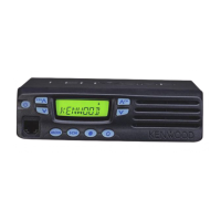
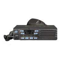
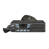
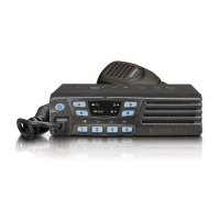
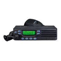
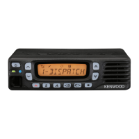
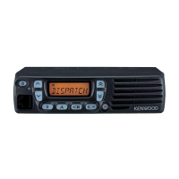
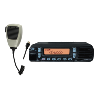
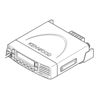
Description of front panel, mic, display, and rear panel.
Description of operating modes and how to enter them.
Details on PC programming and software.
Procedures for cloning and self-programming.
Channel and DTMF settings via panel keys.
Connecting and modifying for ignition sense.
Voice scrambler board connection.
Procedures for detaching panels and cabinets.
Procedures for removing and mounting the display unit.
Description of receiver frequency, IF amp, and system.
Description of power amp, APC, and unlock circuits.
CPU, memory, display, encode/decode, D/A, power supply.
Information about the main microprocessor.
Pin assignments and their functions.
List and description of display unit parts.
List and description of TX-RX unit parts.
List of parts for the display unit.
List of parts for the TX-RX unit.
Visual representation of component assembly.
List of items included in the shipping package.
Required equipment for alignment procedures.
Adjustments for PCB components like power, VCO, IF coil.
Adjusting receiver sensitivity and squelch.
Adjusting transmitter power, frequency, and deviations.
Component and foil side views of the display unit PCB.
Detailed circuit diagrams of the transceiver.
Functional block representation of the transceiver.
Signal levels within the receiver path.
Signal levels within the transmitter path.
Function of pins on CN1 connector.
Function of pins on CN2 connector.
Function of pins on CN3 connector.
Overall operating parameters.
Performance metrics for the receiver.
Performance metrics for the transmitter.
| frequency range type 1 | 146-174 MHz |
|---|---|
| frequency range type 2 | 136-162 MHz |
| channels / groups | 64 CH / 8 GRP |
| channel spacing (wide / narrow) | 25 kHz / 12.5 kHz |
| PLL channel stepping | 2.5 kHz, 5 kHz, 6.25 kHz, 7.5 kHz |
| operating voltage | 13.6 V, DC ±15% |
| current drain standby | 0.4 A |
| current drain receive | 1.0 A |
| current drain transmit | 8.0 A |
| operating temperature range | -30°C ~ +60°C |
| frequency stability | ±2.5 ppm |
| dimensions (W x H x D, without projections) | 160 mm x 43 mm x 107 mm |
| weight (body only, approximate) | 1.0 kg |
| antenna impedance | 50 Ω |
| channel frequency spread type 1 | 28 MHz |
| channel frequency spread type 2 | 26 MHz |
| sensitivity (wide / narrow) | 0.28µV / 0.35µV (12dB SINAD) |
|---|---|
| selectivity (wide / narrow) | 75 dB / 65 dB |
| intermodulation distortion (wide / narrow) | 70 dB / 60 dB |
| spurious response | 75 dB |
| audio output (4Ω, 5% distortion) | 4.0 W |
| RF power output standard version (high / low) | 25W / 5W |
|---|---|
| RF power output high power version (high / low) | 50W / 25W |
| spurious & harmonics | 70 dB |
| modulation (wide / narrow) | 16K0F3E / 11K0F3E |
| FM noise (wide / narrow) | 45 dB / 40 dB |
| audio distortion | Less than 3% |
| microphone impedance | 600Ω |
| frequency range type 1 | 440-480 MHz |
|---|---|
| frequency range type 2 | 400-430 MHz |
| channels / groups | 64 CH / 8 GRP |
| channel spacing (wide / narrow) | 25 kHz / 12.5 kHz |
| PLL channel stepping | 2.5 kHz, 5 kHz, 6.25 kHz, 7.5 kHz |
| operating voltage | 13.6 V, DC ±15% |
| current drain standby | 0.4 A |
| current drain receive | 1.0 A |
| current drain transmit | 14.0 A |
| operating temperature range | -30°C ~ +60°C |
| frequency stability | ±2.5 ppm |
| dimensions (W x H x D, without projections) | 160 mm x 43 mm x 137 mm |
| weight (body only, approximate) | 1.18kg |
| antenna impedance | 50 Ω |
| channel frequency spread type 1 | 40 MHz |
| channel frequency spread type 2 | 30 MHz |
| sensitivity (wide / narrow) | 0.28µV / 0.35µV (12dB SINAD) |
|---|---|
| selectivity (wide / narrow) | 75 dB / 65 dB |
| intermodulation distortion (wide / narrow) | 70 dB / 60 dB |
| spurious response | 75 dB |
| audio output (4Ω, 5% distortion) | 4.0 W |
| RF power output standard version (high / low) | 25W / 5W |
|---|---|
| RF power output high power version (high / low) | 45W / 25W |
| spurious & harmonics | 70 dB |
| modulation (wide / narrow) | 16K0F3E / 11K0F3E |
| FM noise (wide / narrow) | 45 dB / 40 dB |
| audio distortion | Less than 3% |
| microphone impedance | 600Ω |