Do you have a question about the Kenwood TK-7102 and is the answer not in the manual?
Overview of the manual's purpose and intended audience.
Defines the manual's coverage and currency, mentioning service bulletins.
Instructions for ordering parts, including required identification information.
Essential safety guidelines for operating and servicing the equipment.
Key steps before installing the radio, including unpacking and licensing.
Steps to check radio operation and accessories before installation.
Guidance on planning antenna, radio, and wiring placement in a vehicle.
Considerations for antenna systems and radio location for control stations.
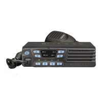
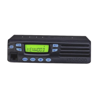
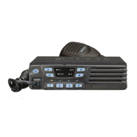
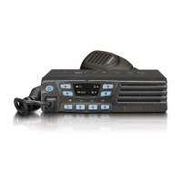
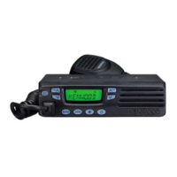
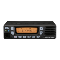
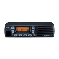
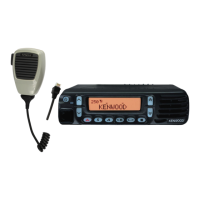
Introduces front panel, microphone, display, and rear panel controls and indicators.
Details the function of each button and LED on the front panel.
Explains the microphone jack and PTT switch usage.
Lists available functions for programmable keys, like Emergency and Key Lock.
Explains the meaning of the TX, BUSY, and channel indicator LEDs.
Identifies antenna and external speaker connections on the rear panel.
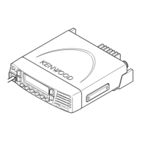
Summarizes the TK-7102's conventional format and programmable features.
Further details on POWER, CHANNEL, MONITOR, VOLUME keys and BUSY/TX LED.
Explains functions for programmable keys like Emergency, Key Lock, Monitor, Scan.
Details how to start, stop, and manage scan functions, including revert channels.
How to temporarily delete channels during scan and how they are restored.
Explains Time-out Timer, PTT ID, Off Hook Decode, and TOT settings.
Covers DTMF capabilities for signalling, including SP Unmute and Auto Reset.
Lists and describes different operating modes like User, PC, Clone, and Test modes.
Procedures for entering User, PC, and Clone modes via button combinations.
Details the preface and connection procedure for programming via PC.
Description of the optional cable for PC programming.
Information about the programming software disk and its capabilities.
How to transfer and modify data using an IBM PC and KPG-70D.
Procedure for transferring programming data between radios using a cloning cable.
Explains the receiver's double conversion IF system and frequency generation.
Details the double superheterodyne receiver, including RF amplifier and first mixer stages.
Describes the IF signal amplification and filtering process in the receiver.
How the CPU switches between ceramic filters for wide and narrow signals.
Describes the audio signal path from IF to AF amplifier and output.
Explains how the squelch detects noise and controls the CPU.
Details the PLL circuit for generating local oscillator and RF signals.
How the circuit detects PLL lock status and controls transmission.
Describes the transmitter's FM modulation and carrier signal amplification.
Details the transmit signal path from VCO to the low-pass filter and power module.
Automatic transmission power control circuit for stabilizing output.
How the CPU controls the display LEDs for BUSY, TX, and function keys.
Lists the tasks performed by the CPU, including WIDE/NARROW, AF, DTMF, PLL control.
Explains the EEPROM's role in storing adjustment data and CPU control.
How the microprocessor detects key presses via a matrix.
How QT/DQT and DTMF signals are processed and summed for transmission.
How QT/DQT and DTMF signals are received and decoded.
Details the D/A converter's role in adjusting various voltage levels.
Describes the power supply activation and overvoltage protection circuit.
Lists pin assignments and functions for the 784214AGCXXX microprocessor.
Lists and describes components found on the display unit (X54-3340-20).
Lists and describes components found on the TX-RX unit (X57-6290-20).
Lists parts for the main TK-7102 unit, including cabinets and panels.
Lists components and their part numbers for the TX-RX unit.
Lists components and their part numbers for the display unit.
Lists essential test equipment and their specifications for radio alignment.
Details the tuning cable and PC mode connection for audio injection.
Diagram and pinout for the test cable used with the microphone input.
Identifies locations for switch adjustments and component-level tuning points.
Guidance on the correct orientation for mounting the fuse.
Importance of readjusting the transceiver after EEPROM data changes.
Specific instructions for mounting the AF PA IC (IC102) and speaker cable.
Details adjustments for VCO lock voltage, IF Coil, and RF Band-pass filter using KPG-70D.
Procedures for adjusting sensitivity and squelch levels using test equipment.
Lists the TX and RX frequencies used for testing and adjustment.
Details adjustments for frequency, power, deviation, and microphone sensitivity.
Shows component placement and reference designators on the display unit PCB.
Identifies components and their locations on the TX-RX unit's component side.
Identifies components and their locations on the TX-RX unit's foil side.
Illustrates the functional blocks and signal flow for the display unit.
Shows the main functional blocks and interconnections within the TX-RX unit.
Shows signal levels at various points in the receiver section.
Shows signal levels at various points in the transmitter section.
Lists the pin functions for the CN1 connector on the TX-RX unit.
Lists the pin functions for the J1 connector on the TX-RX unit.
Lists the pin functions for the J1 connector on the control unit.
Covers frequency range, channels, voltage, dimensions, and weight.
Details receiver performance metrics like sensitivity, selectivity, and audio output.
Details transmitter performance metrics like power output, modulation, and distortion.
| Frequency Range | 136-174 MHz |
|---|---|
| Channel Capacity | 128 channels |
| Operating Temperature | -30°C to +60°C |
| Channel Spacing | 12.5 kHz / 25 kHz |
| Modulation | 16K0F3E |
| Battery Life | N/A (Mobile Radio) |