EasyManua.ls Logo

Kenwood TK-7102H Service Manual

Kenwood TK-7102H
41 pages
To Next Page IconTo Next Page
Page #1 background imageLoading...
Page #1 background image
© 2001-11 PRINTED IN JAPAN
B51-8610-00
(
N
)
1051
VHF FM TRANSCEIVER
TK-7102H
SERVICE MANUAL
GENERAL .................................................. 2
OPERATING FEATURES .......................... 3
REALIGNMENT ......................................... 7
DISASSEMBLY FOR REPAIR ................... 9
CIRCUIT DESCRIPTION .......................... 10
SEMICONDUCTOR DATA ...................... 15
DESCRIPTION OF COMPONENTS ........ 17
PARTS LIST ............................................. 19
EXPLODED VIEW.................................... 25
PACKING ................................................. 26
ADJUSTMENT ........................................ 27
TERMINAL FUNCTION ........................... 32
PC BOARD VIEWS
DISPLAY UNIT (X54-3340-20) ............ 33
TX-RX UNIT (X57-6380-20) ................ 35
SCHEMATIC DIAGRAM.......................... 41
BLOCK DIAGRAM ................................... 45
LEVEL DIAGRAM .................................... 47
SPECIFICATIONS .................................... 49
CONTENTS
Panel assy
(A62-0942-03)
Front glass
(B10-2668-03)
Cabinet
(A01-2181-01)
Chassis
(A10-4048-11)
Key top
(K29-9065-01)
Modular jack
(E08-0877-05)

Other manuals for Kenwood TK-7102H

Question and Answer IconNeed help?

Do you have a question about the Kenwood TK-7102H and is the answer not in the manual?

Kenwood TK-7102H Specifications

General IconGeneral
Frequency Range136-174 MHz
Channel Capacity128
Channel Spacing12.5 / 25 kHz
Operating Temperature-30°C to +60°C
Battery LifeN/A (Mobile Transceiver)
ModulationFM

Summary

General Information

Personnel Safety Precautions

Essential safety measures for operation and servicing.

Operating Features

Front Panel Controls and Functions

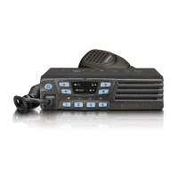
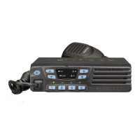
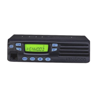
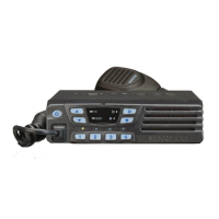
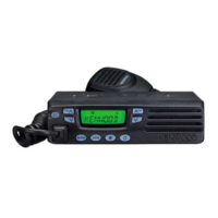
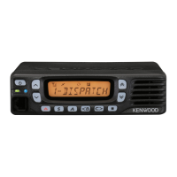
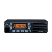
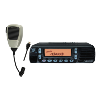
Describes controls, indicators, and microphone interface.

Front Panel Controls and Programmable Keys

Detailed explanation of specific controls and programmable key functions.

Realignment Procedures

Operating Modes and Entry

Describes different operating modes and how to enter them.

Cloning and Data Management

Details cloning, password, software, and PC programming.

Disassembly for Repair

Circuit Description

Frequency Configuration and PLL

Explains frequency generation, PLL, and VCO.

PLL and VCO Circuits

Detailed explanation of PLL synthesizer, VCO, and unlock circuit.

Transmitter System and Control

Covers power amplifier, APC circuit, control circuit, and memory.

Semiconductor Data

Microprocessor Pin Functions

Lists pins and functions for the TX-RX Unit IC6 microprocessor.

Description of Components

Parts List

Exploded View

Packing Information

Adjustment Procedures

Required Test Equipment and Specifications

Lists necessary equipment and their major specifications for alignment.

Transmitter Section Adjustments

Details frequency, power, balance, sensitivity, and deviation adjustments.

Terminal Function

PC Board Views

Schematic Diagram

Overall Circuit Schematic

Provides a detailed schematic of the transceiver's circuitry.

Block Diagram

System Block Diagram

Illustrates the main functional blocks and signal flow of the transceiver.

Level Diagram

Specifications

General and Receiver Specifications

Covers frequency, channels, voltage, sensitivity, selectivity, and intermodulation.

Transmitter Specifications

Details power output, modulation, FM noise, and frequency stability.

Related product manuals