Do you have a question about the Kenwood TK-768H and is the answer not in the manual?
Discusses the manual's scope and purpose for experienced technicians.
Provides guidelines for ordering replacement parts, including part identification numbers.
Lists essential safety precautions for operating and servicing the equipment to prevent injury.
Mentions the radio's design for easy servicing and refers to internal diagrams.
Explains requirements for programming, including PC, interface, and software.
Lists and describes various operating modes (User, Dealer, Panel Test, PC Mode, etc.) and their functions.
Explains the procedure to access each operating mode by pressing specific buttons during power-on.
Details how to set channels and functions without FPU, including setting initial mode and channel selection.
Describes the process of setting channels, frequencies, and signaling parameters using the transceiver's keys.
Lists configurable items for channel selection, RX/TX frequency, QT, DTMF signaling, and PTT ID with their settings and displays.
Explains how to set common transceiver functions without the FPU, including entering the mode and changing settings.
Lists detailed function settings, including F version, monitor, talk around, signaling, and others, with display values.
Continues the list of function settings, covering items like priority channel, look back, revert channel, TX dwell time, and DTMF signaling.
Describes how to disable self-programming, mentioning FPU use and shift-prohibit cancellation.
Explains how to enter Panel Test Mode, its display behavior, and how to select versions using keys.
Details the operation of Test Mode Channel, including version selection and key functions for channel operations.
Provides frequency data for different models (M, DM, M2, DM2) used during test mode operations.
Lists signaling options (None, QT, DTMF) and their corresponding encode/decode settings for test mode.
Describes how to enter Panel Tuning Mode, the display states, and how to select versions and channels/signaling.
Lists key functions for selecting channels and tuning items within Panel Tuning Mode.
Lists all tuning items (Frequency, RF power, deviation, sensitivity, squelch) with valid ranges and remarks.
Illustrates the state transitions during panel tuning, showing how to navigate between adjustment items.
Introduces transceiver programming using IBM PC, interface (KPG-4), and software (KPG-29D).
Describes the KPG-4 PC programming interface cable, its function, and connection.
Details the KPG-29D programming software, its MS-DOS requirements, and data handling capabilities.
Explains data programming mode, how it's entered, and its use with PC/KPG-29D for tuning.
Describes the procedure for transferring programmed data between transceivers using a microphone cable.
Explains how to initialize the transceiver's EEPROM data, noting what is and isn't reset.
Details the steps to perform a memory reset by pressing specific keys during power-on.
Describes the KCT-19 accessory cable for external equipment, its connector, and signal lines.
Provides steps for installing the KCT-19 cable inside the transceiver case.
Details inserting the KCT-19 cable into the chassis and ensuring wire harness band placement.
Describes relocating the DC cord bushing in the chassis after cable installation.
Explains connecting the KCT-19 to the TX-RX unit as shown in Figure 2.
Describes connecting the KCT-19 to external accessories using crimp terminals and square plugs.
Lists the functions of the 15-pin ACC terminal pins (A-1 to A-15) and their corresponding signal names and operations.
Describes the KCT-18 as an optional cable for ignition function, allowing power control via car ignition key.
Details connecting the KCT-18 to the transceiver by inserting its terminal into the KCT-19's square plug.
Explains how to modify the transceiver to control power and Horn Alert using the ignition key by setting jumper resistors R5 and R6.
Provides a chart showing the R5 and R6 jumper settings for different power and Horn Alert control configurations.
Describes the emergency mode feature, allowing automatic transmission of emergency signals via a foot switch.
Outlines the emergency mode, how it's activated, and potential use of KAP-1 for external warnings.
Illustrates the emergency mode system flow, showing activation, channel selection, and reset procedures.
Details the procedure for modifying the transceiver, including installing the foot switch and changing the power switch circuit.
Explains how to modify the circuit for the KAP-1 unit to enable emergency Horn/Light drive relay output.
Instructs on installing the modified KAP-1 unit in the transceiver and sending output signals.
Introduces the KAP-1 unit as an option for Horn Alert and Light functions, detailing installation and modification.
Provides steps for installing the KAP-1 switch unit and connecting its cables to the transceiver.
Explains modifications to the transceiver for Horn Alert function, including CPU signals and relay output.
Mentions connecting the KCT-19 C connector to CN5 on the TX-RX unit if HR2 is not needed.
Describes the KES-3 as an optional external speaker for the 3.5mm-diameter speaker jack.
Details how to connect the KES-3 external speaker to the transceiver's rear speaker jack.
Explains how to mount the control panel upside down for specific car installations.
Explains the receiver's double-conversion superhet configuration and the signal path for frequency generation and transmission.
Describes the RF unit's signal path, including antenna switch, bandpass filters, RF amplifier, and first mixer.
Details the IF unit's components, including crystal filters, IF amplifiers, and the second IF system IC.
Explains the audio amplifier unit's signal path, including filters, de-emphasis, and volume control.
Describes the squelch circuit, its interaction with the CPU, and how it controls noise levels.
Explains the final amplifier's role in amplifying the PLL signal to output power and its control mechanism.
Traces the signal path from the microphone through mute switch, filters, summing amplifier, and D/A converter.
Explains the final amplifier's role in amplifying the PLL signal to output power and its control mechanism.
Describes the Automatic Power Control (APC) circuit, its voltage application, and its function in maintaining constant transmit current.
Explains how the PLL generates transmit/receive signals, the role of VCO, Q5/Q2 switching, and phase comparison for frequency control.
Describes the PLL unlock detection signal, its monitoring by the CPU, and how the CPU prevents transmission when unlocked.
Mentions that the CPU contains an LCD driver for the 7-segment, 8-digit LCD display.
Outlines the control section's components (CPU, peripherals) and lists the CPU's main functions.
Describes the 8-Kbit EEPROM (IC201) used for storing adjustment and backup data.
Explains IC10 as an interface IC for expanding CPU output ports.
Details IC6 as a semi-fixed-resistor converter used for setting various parameters like RX sensitivity and TX power.
Explains how the CPU transmits encode data for QT and DTMF signals, and their path through filters and amplifiers.
Describes how RX decode data (QT, DTMF) is processed, including signal input to CPU and DTMF decoding.
Explains PLL data output from CPU pins and its input to the PLL IC for channel or transmission/reception changes.
Details the horn switch circuit (Q13, Q14, Q24) controlling the horn relay and its operation, including KAP-1 support.
Explains the power supply circuit, including overvoltage protection (D4) and protection against incorrect voltage connection (Q2, Q3, Q4).
Identifies the microprocessor used in the TX-RX unit and provides its terminal connection diagram.
Lists the function of each pin on the microprocessor, including I/O type and operational conditions.
Identifies the PLL system IC and shows its terminal connection diagram and block diagram.
Illustrates the internal block diagram of the PLL system IC, showing its major functional blocks and data flow.
Identifies the power module part numbers and shows its terminal connection diagram and equivalent circuit.
Identifies the reset switch IC and shows its terminal connection diagram and block diagram.
Lists components used in the TX-RX unit, including ICs, Qs, and Ds, with their part numbers and functions.
Lists components associated with the VCO unit, specifying part numbers and their functions for different destinations.
Provides details on capacitors, including type, shape, temperature coefficient, value coding, and dimension codes.
Explains the color-coding system for capacitor temperature coefficients and their corresponding ppm/°C values.
Details the coding system for capacitor tolerance (percentage) and their values.
Explains the coding system for capacitor voltage ratings.
Shows dimension codes and their corresponding sizes for chip capacitors and resistors.
Explains the coding for chip resistors, including type, dimension, wattage, and tolerance.
Explains the coding for chip resistors, including type, dimension, wattage, and tolerance.
Details the coding system for normal carbon resistors, covering type, dimension, wattage, and tolerance.
Lists parts for the TX-RX unit, including ICs, transistors, capacitors, and connectors, with part numbers and destinations.
Continues the parts list for the TX-RX unit, detailing resistors (R238-R522) with their part numbers and specifications.
Continues the parts list for the TX-RX unit, detailing resistors (R238-R522) with their part numbers and specifications.
Lists parts for the TX-RX unit and VCO section, including ICs, transistors, and capacitors, with part numbers and destinations.
Continues listing components for the VCO section, detailing capacitors (C12,13-C27) and resistors (R1-R15) with their part numbers and destinations.
Shows an exploded view of the transceiver's main assembly, with numbered parts and their corresponding labels.
Illustrates the packing configuration of the transceiver and its accessories, showing the placement of components in the box.
Lists the necessary test equipment and their major specifications for performing alignment procedures on the transceiver.
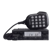
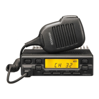
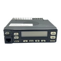
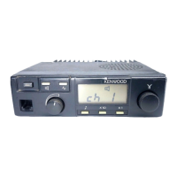
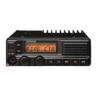
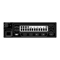
Identifies the location of adjustment controls on the front panel of the transceiver.
Explains the various indicators and symbols displayed on the transceiver's screen during operation and adjustment.
Lists tuning items, their descriptions, valid ranges, and remarks for performing transceiver adjustments.
Illustrates the state transitions during panel tuning, showing how to navigate between adjustment parameters.
Details adjustment procedures for the common section, including memory frequency, signaling settings, and panel test/tuning modes.
Explains how to set the panel test mode by holding specific switches during power-on.
Explains how to set the panel tuning mode by holding specific switches during power-on.
Describes how to check PLL lock voltage in panel test mode for transmit and receive.
Details adjustment procedures for the receiver section, including sensitivity, squelch, and their required test equipment and specifications.
Details adjustment procedures for the transmitter section, including frequency, power, and signaling balance, with required equipment and specs.
Describes the adjustment procedure for maximum deviation, including tuning items, test equipment, and specifications.
Explains the procedure for adjusting microphone sensitivity, including test conditions and specifications.
Details the adjustment for QT deviation, including tuning items, test equipment, and specifications.
Outlines the procedure for checking DTMF deviation, including test conditions and specifications.
Lists and describes the function of each terminal pin for the TX-RX unit (A/2) and the VCO unit.
Lists and describes the function of each terminal pin for the TX-RX unit (B/2) and the VCO unit.
Lists and describes the function of each terminal pin for the TX-RX unit (A/2) and the VCO unit.
Provides component-side and foil-side views of the VCO printed circuit board.
Shows the component layout on the TX-RX Unit (A/2) printed circuit board.
Shows the foil layout on the TX-RX Unit (A/2) printed circuit board.
Shows both component and foil side layouts for the TX-RX Unit (A/2) PCB.
Shows the foil layout on the TX-RX Unit (A/2) printed circuit board.
Shows both component and foil side layouts for the TX-RX Unit (B/2) PCB.
Shows both component and foil side layouts for the TX-RX Unit (B/2) PCB.
Shows the schematic diagram for the TX-RX unit, covering TX-RX section, control section, and VCO.
Presents a block diagram illustrating the overall system architecture and signal flow between major units.
Details the block diagram for the TX-RX section of the unit, showing component interconnections.
Details the block diagram for the control section of the unit, showing component interconnections.
Shows a detailed block diagram of the transceiver's main sections (VCO, TX-RX, Processor, etc.) and their interconnections.
Provides a detailed schematic for the TX-RX section, showing component placements and connections.
Shows the component and foil side views of the TX-RX Unit (B/2) PCB, with grid coordinates for component location.
Displays the component layout on the TX-RX Unit (B/2) PCB.
Shows both component and foil side layouts for the TX-RX Unit (B/2) PCB.
Shows both component and foil side layouts for the TX-RX Unit (B/2) PCB.
Details the circuit diagram for the TX-RX Unit's control section, showing component interconnections.
Continues the circuit diagram for the TX-RX Unit's control section, illustrating component interconnections.
Continues the circuit diagram for the TX-RX Unit's control section, illustrating component interconnections.
Details the circuit diagram for the TX-RX section, showing ICs, transistors, and connectors, with cross-references.
Details the block diagram of the TX-RX unit, illustrating the interaction between different sections like TX-RX, Control, and VCO.
Shows a detailed block diagram of the transceiver's main sections (VCO, TX-RX, Processor, etc.) and their interconnections.
Illustrates the signal levels at various points in the RX and TX sections, indicating measurement methods.
Describes the KAP-1 unit as an optional accessory for horn alert and switching relay functions.
Lists the parts included in the KAP-1 unit, such as switch units, connectors, and transistors.
Provides the circuit diagram for the KAP-1 switch unit, showing component connections and layout.
Displays component-side and foil-side views of the KAP-1 switch unit's printed circuit board.
Lists the technical specifications for the TK-768/H transceiver, including frequency range, channels, power, and performance metrics.
Details receiver performance metrics like sensitivity, selectivity, intermodulation, and audio output.
Details transmitter performance metrics like RF power output, modulation, and frequency stability.
| Frequency Range | 136-174 MHz |
|---|---|
| Output Power | 5W / 1W |
| Channel Spacing | 12.5/25 kHz |
| Weight | 320 g |
| Operating Temperature | -30°C to +60°C |
| Modulation | 16K0F3E |
| Channels | 128 |