Do you have a question about the Kenwood TK-768 and is the answer not in the manual?
Manual covers service info for experienced technicians.
Includes full part ID number for replacement orders.
Precautions for safe operation and handling.
Radio designed for easy servicing via diagrams and procedures.
Oscillator stability not guaranteed with non-Kenwood channel elements.
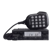
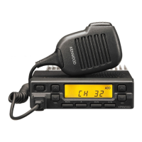
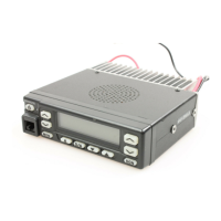
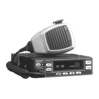
Lists models, frequency ranges, TX power, signaling, and mic types.
Programming requires PC, interface, and software.
Lists optional accessories like KAP-1, KES-3, KCT-19, KCT-18.
Lists and describes various operating modes.
Mode for customer use as a transceiver.
Mode for dealer settings and checks.
Mode for checking fundamental characteristics.
Mode for radio tuning.
Communication mode with PC for data programming.
Mode for writing/reading frequency and feature data.
Mode for transferring programmed data between transceivers.
Instructions to access different operating modes.
Allows dealer to set functions without FPU.
Procedure for setting channels and functions.
Allows setting common functions for all channels without FPU.
Prohibits user writing and shifting modes.
Method to cancel shift-prohibit.
Mode where all LCD segments light and beeper sounds.
Operation when CHANNEL DOWN key is pressed in VERSION SELECT mode.
Mode for tuning with display indicators.
Explains PC-based programming setup.
Details the PC programming interface cable.
Describes the KPG-29D software.
Mode to write data into transceiver EEPROM.
Transfers data between transceivers using a microphone cable.
Cable for connecting external equipment.
Step-by-step guide for installing the cable.
Optional cable for ignition function.
Steps to connect KCT-18 to transceiver.
Modifies transceiver for ignition key power/Horn Alert control.
Transceiver modification for emergency mode.
Transceiver modification for emergency mode.
Steps to install foot switch and change power switch circuit.
Modifies circuit for KAP-1 Horn/Light drive.
Enables Horn Alert and Light functions.
Procedure for installing KAP-1 unit.
Modifies transceiver for Horn Alert.
Connecting HR2 or speaker output via KCT-19.
Connects KES-3 external speaker.
KES-3 is a 3.5mm speaker.
Mounts panel with internal speaker facing down.
Explains receiver and transmitter signal paths.
Details the RF unit's signal processing.
Describes signal path from antenna to first mixer.
Explains the first and second IF stages and FM detector.
Describes signal amplification and volume adjustment.
Explains how the squelch circuit operates with the CPU.
Covers microphone amplifier and final output stages.
Details microphone signal processing path.
Amplifies signal to output level and controls transmit current.
Automatic Power Control circuit explanation.
Explains VCO/PLL operation for signal generation.
Details VCO/PLL signal generation and control.
How CPU monitors PLL status and prevents transmission.
Describes the LCD driver and 7-segment display.
Explains CPU functions for controlling TX-RX unit.
EEPROM for storing adjustment and backup data.
Interface IC for expanding CPU output ports.
Used for setting RX sensitivity, power, modulation, etc.
CPU transmits encode data for QT and DTMF.
QT/DTMF data output and processing.
CPU digitizes and decodes QT and DTMF signals.
QT signal processing for CPU decode.
DTMF decoding via IC410.
PLL data output for channel/mode switching.
Controls horn relay for external alert function.
Power supply circuit protection and operation.
Details of the microprocessor and its pins.
Lists pin numbers, names, I/O, and function.
Details of the PLL IC and its connections.
Details of the power module.
Details of the reset switch.
Lists components on the TX-RX unit.
Lists components for the VCO unit.
Details capacitor types, values, and ratings.
Table for capacitor temperature coefficients.
Table for capacitor tolerances.
Table for capacitor voltage ratings.
Lists chip capacitor part numbers and values.
General section for resistors.
Lists chip resistor part numbers and values.
Lists carbon resistor part numbers and values.
Lists parts for the TX-RX unit.
Lists parts for the VCO unit.
Lists necessary test equipment and specifications.
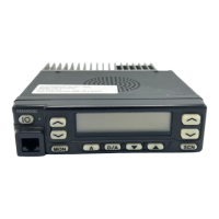
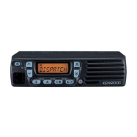
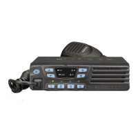
Identifies control panel buttons and their functions.
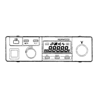
Identifies front panel controls.
Explains display indicators and their meanings.
Lists adjustable parameters and their ranges.
Diagram showing the tuning mode flow.
General adjustments and test procedures.
Procedure for setting memory frequencies.
Setting up receiver and transmitter sections.
Test conditions for receiver alignment.
Test conditions for transmitter alignment.
How to enter Panel Test Mode.
How to enter Panel Tuning Mode.
Procedure for checking PLL lock voltage.
Detailed adjustment steps for receiver parameters.
Adjusts receiver sensitivity.
Adjusts squelch threshold.
Detailed adjustment steps for transmitter parameters.
Adjusts transmitter frequency.
Checks maximum transmitter power output.
Adjusts transmitter power levels.
Adjusts signaling balance.
Adjusts maximum frequency deviation.
Adjusts microphone sensitivity.
Adjusts QT deviation.
Checks DTMF deviation.
Lists terminals and functions for TX-RX unit.
Lists terminals and functions for control section.
Lists terminals and functions for VCO unit.
Component layout for VCO board.
Foil layout for VCO board.
Component layout for TX-RX unit (A/2).
Circuit diagram for TX-RX section.
Component and foil layout for TX-RX unit (B/2).
Circuit diagram for control section.
Circuit diagram for TX-RX section.
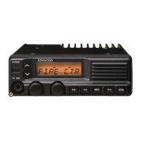
Unit description and overview.
Highlights horn alert function.
Controls HA function via external equipment.
Schematic of the KAP-1 circuit.
Component and foil layouts for KAP-1.
General specifications for frequency, channels, voltage, etc.
Receiver performance specifications.
Transmitter performance specifications.
| Type | Mobile |
|---|---|
| Frequency Range | 136-174 MHz |
| Channel Capacity | 128 |
| Channel Spacing | 12.5/25 kHz |
| Modulation | 16K0F3E / 11K0F3E |
| Battery | N/A (Mobile unit) |
| Battery Life | N/A (Mobile unit) |