EasyManua.ls Logo

Kenwood TK-690H Service Manual

Kenwood TK-690H
81 pages
To Next Page IconTo Next Page
Page #1 background imageLoading...
Page #1 background image
© 2001-7 PRINTED IN JAPAN
B51-8460-10
(
N
)
1031
TK-690H(B)
KCH-10
KCH-11
VHF FM TRANSCEIVER
TK-690H
(
B
)
SERVICE MANUAL
Cabinet (Upper)
(A01-2163-01)
Panel assy
(A62-0606-13)
Panel assy
(A62-0607-13)
Cabinet (Lower)
(A01-2164-01)
Knob
(K29-4664-04) x 2
Knob
(K29-4664-04) x 2
REVISED
This service manual applies to products with 30500001 or subsequent serial numbers. (KCH-10 and KCH-11 are applicable to
the productions June 2001 and after.)
In terms of the products with the serial numbers earier than 30500001, refer to the TK-690H(B) service manual as per part
No. B51-8460-00.

Other manuals for Kenwood TK-690H

Question and Answer IconNeed help?

Do you have a question about the Kenwood TK-690H and is the answer not in the manual?

Kenwood TK-690H Specifications

General IconGeneral
Frequency Range136-174 MHz
Channel Capacity16
Modulation TypeFM
Channel Spacing25 kHz/12.5 kHz
Power Supply13.8V DC

Summary

VHF FM TRANSCEIVER TK-690H(B) SERVICE MANUAL REVISED

Contents and General Section

Personnel Safety Precautions

Safety precautions for operating and servicing the equipment.

General Pre-Installation and Service Notes

Pre-Installation Considerations

Steps to take before installing the radio, including unpacking and planning.

System Set-up Procedures

System Configuration Flowchart

Visual guide for configuring the transceiver based on operational needs.

Operating Features and Controls

Controls and Functions Overview

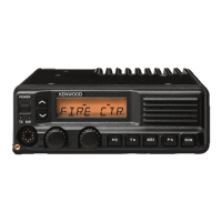
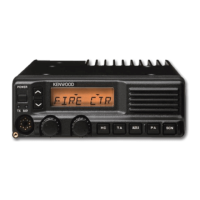
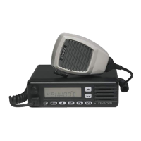
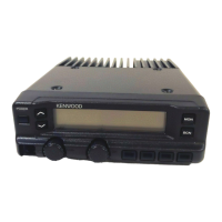
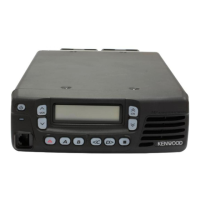
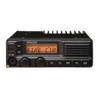
Detailed description of controls on the basic and full function panels.

Control and Key Function Descriptions

Explains the function of each control and key on the panels.

Detailed Operating Features

Function Descriptions

Detailed explanation of various functions like Squelch, Scrambler, AUX ports.

Advanced Operating Features

Function Descriptions (Continued)

Describes functions like MIC PTT, Receive, Transmit, and Scan operation.

Scan and Alerting Features

Scan Feature Operation Details

Details how the scan feature is initiated, stops, and operates.

Advanced Operating Functions

Emergency Call (EMG) Function

Entering Emergency Mode and transmitting emergency calls.

Signaling and Control Features

Busy Channel Lockout (BCL)

Prevents interference by checking channel usage before transmitting.

Additional Operating Functions

Accessory Programmable Function Port (PF Port)

Overview of programmable PF ports and their functions.

PF Input Port Functions

Details the functions programmable for PF input ports.

PF Output Port Functions

Details the functions programmable for PF output ports.

Timed Power Off Function

Automatic power-off function based on ignition status.

Emergency Operation Details

Information related to emergency operations.

Advanced Operating and Programming Features

Emergency Feature Configuration

Details on Emergency Mode Type, Type, DTMF ID, Fleet, and Call ID.

Data Programming via PC

Preparation and connection for PC programming.

KPG-43 Programming Interface Cable

Description of the KPG-43 interface cable.

KPG-44D Programming Software

Description of the KPG-44D programming software.

Operating Mode Selection

Overview of available operating modes.

Operating Modes and PC Tuning

Operating Mode Descriptions

Details the functions of various modes like User, PC, Panel test, Clone.

Entering Operating Modes

Step-by-step instructions for entering each operating mode.

PC Tuning Mode Configuration

Instructions for modifying the KPG-43 cable for PC tuning.

Cloning Procedures

Clone Mode Overview

Explanation of All Clone Mode and Group Clone Mode.

Installation Guide

Installation of Optional Functions

Ignition Sense Cable and External Speaker Installation

External Speaker and Remote Kit Connections

Control Head Audio Output and Terminals

Installation Component References

Disassembly Procedures

Control Unit and Accessory Connector Disassembly

Display Unit Disassembly

Circuit Description Overview

Transmitter Circuit

Describes the transmitter section of the radio.

Final Amplifier Section

Details the final amplifier circuitry and protection circuits.

Receiver Circuit

Describes the receiver section of the radio.

Receiver and Squelch Circuitry

RF Filters, PLL, and Control Circuitry

VCO/PLL Circuit Description

Explains the Voltage Controlled Oscillator and Phase-Locked Loop circuit.

Control Circuit Operations

Describes the control unit's microprocessor functions.

Circuit Description: D/A Converter, Power Supply, and Signaling

Power Supply Circuit Description

Describes the power supply circuit and protection functions.

Signalling Circuitry

Explains the encode and decode circuits for signalling.

Display Unit Circuitry

KCH-10 Display Unit Components

Details the components and functions of the KCH-10 display unit.

KCH-11 Display Unit Circuitry

KCH-11 Display Unit Components

Details the components and functions of the KCH-11 display unit.

Semiconductor Data for Control Unit

Microprocessor IC516 Terminal Functions

Terminal functions for the control unit microprocessor.

IC516 Pin Assignments and Functions

Pin assignments and functions for IC516.

Semiconductor Data for Display Unit and Shift Register

Microprocessor IC4 Terminal Functions

Terminal functions for the display unit microprocessor.

IC4 Pin Assignments and Functions

Pin assignments and functions for IC4.

Semiconductor and Component Data

Final Unit Component Usage

Component usage and conditions for the final unit.

TX-RX Unit Component Usage

Component usage and conditions for the TX-RX unit.

Component Data for Control Unit

Control Unit Component Usage

Component usage and conditions for the control unit.

Component Data for Display Units

KCH-10 Display Unit Component Usage

Component usage and conditions for the KCH-10 display unit.

KCH-11 Display Unit Component Usage

Component usage and conditions for the KCH-11 display unit.

Parts List Overview

Final Unit Parts List

Parts list for the final unit.

TX-RX Unit Parts List

Parts list for the TX-RX unit.

Detailed Parts List: Final and TX-RX Units (Continued)

Final Unit Parts List (Continued)

Parts list for the final unit (continued).

Detailed Parts List: TX-RX, NB, and KCH-10 Components

TX-RX Unit Parts List (Continued)

Parts list for the TX-RX unit (continued).

Detailed Parts List: Display Units

KCH-10 Display Unit Parts List

Parts list for the KCH-10 display unit.

Detailed Parts List: KCH-11 Display Unit

KCH-11 Display Unit Parts List

Parts list for the KCH-11 display unit.

Exploded Views of Transceiver and Panels

TK-690H(B) Main Unit Exploded View

Exploded view of the main transceiver unit and its sub-assemblies.

KCH-10 Exploded View Details

KCH-10 Assembly Components

Detailed exploded view of the KCH-10 unit.

KCH-11 Exploded View Details

KCH-11 Assembly Components

Detailed exploded view of the KCH-11 unit.

Adjustment Procedures Overview

Key Functions in Test and Tune Modes

Lists key functions and their roles in test and tune modes.

Panel Test Mode Description

Overview of panel test mode for measurements and signaling decoding.

Panel Tune Mode Description

Overview of panel tune mode for transceiver adjustment.

Tuning Items and Control Diagrams

Tuning Items and Display Values

Lists tuning items, their basic and full display values.

Adjustment Test Equipment and Cable Diagrams

Test Equipment for Alignment

Lists necessary test equipment and their specifications for alignment.

Adjustment Points and Common Settings

Frequency Adjustment Table

Table for adjusting frequencies across channels and bands.

Test Signalling Channel Settings

Table for setting test signalling channels and tones.

Specific Adjustment Procedures

RF Power, Deviation, and Sensitivity Adjustments

Signaling and Sensitivity Adjustment Procedures

Squelch and Noise Blanker Adjustment

Terminal Functionality

Final Unit Terminal Functions

Terminal functions for the final unit.

Control Unit Terminal Functions

Terminal functions for the control unit.

TX-RX Unit Terminal Functions

Terminal functions for the TX-RX unit.

Display Unit and Connector Terminal Functions

Display Unit Terminal Functions (KCH-10/KCH-11)

Terminal functions for the display units.

Terminal Function Details

25-Pin D-sub Connector Terminal Functions

Terminal functions for the 25-pin D-sub connector.

PC Board Views: Control Unit

Control Unit Component and Foil Side Views

Component layout of the control unit (both sides).

PC Board Views: Control Unit (Continued)

Control Unit Component and Foil Side Views (Continued)

Component layout of the control unit (both sides, continued).

Wiring Diagram

Wiring Diagram Overview

Shows wiring connections between major units.

Block Diagram of TK-690H(B)

TK-690H(B) Overall Block Diagram

Overall block diagram of the transceiver system.

Technical Specifications

General Specifications

General electrical and environmental specifications.

Receiver Specifications

Receiver performance specifications.

Transmitter Specifications

Transmitter performance specifications.

Related product manuals