Do you have a question about the Kenwood TM-201B and is the answer not in the manual?
Lists microphone, speaker, kits, power cord, fuse, and manual.
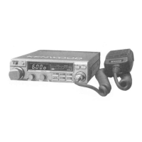
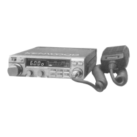
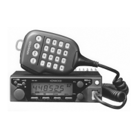
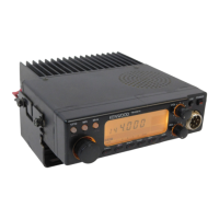
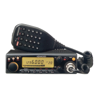
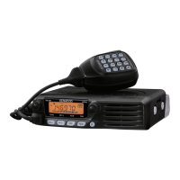
Highlights the transceiver's portable and slim form factor.
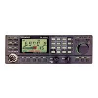
Details the multi-frequency control capabilities.
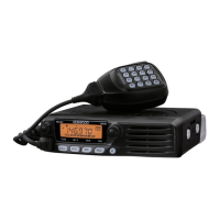
Focuses on high reliability via PC boards and sensitivity.
Covers repeater operation, extended range, and sound quality.
Introduces main controls like Tuning, VOL/POWER, SQUELCH, and the Keyboard section.
Details MR/M1 and MS/M2 keys for memory and scan operations.
Explains MHz/M3, M/M4, AL/M5, and A/B keys for advanced functions.
Details MIC connector and COM key functions.
Covers the HI/LOW power switch and various display indicators.
Describes frequency, scan, VFO B, MR, ALERT, ON AIR, BUSY, and S&RF meter indicators.
Explains the REV and TX OFFSET switches for mode selection.
Details rear panel connectors (antenna, power, speaker) and side panel remote jack.
Details UP/DWN, PTT, and Touch-Tone keys for USA models.
Details UP/DWN and PTT keys for non-USA models.
Advice on selecting and adjusting antennas for optimal performance.
Instructions for vehicle installation, including wiring and location.
Step-by-step instructions for mounting the communications speaker.
Covers roof-top, trunk lid systems, and coax cable routing.
Specifies DC power supply needs and recommended models.
Discusses fixed station antenna types and SWR impact.
Guidance on receiving signals, using squelch, and tuning.
How to transmit, including precautions and power settings.
Steps to store frequencies in simplex memory channels.
Steps to store frequencies in split channel memories.
How to initiate and perform memory channel scans.
Setting frequency limits for programmable scan operation.
Managing scan start, stop, resume, and direction changes.
Procedures for opening the transceiver unit.
How to adjust the beeper volume.
Information on the lithium battery and microcomputer reset.
Instructions for using the optional FC-10 frequency controller.
Lists accessories and parts for the TU-3/TU-3A unit.
Details on setting tone frequencies and installing the unit.
Explains how the TX final module is protected against high SWR.
Covers battery precautions, ordering parts, and service guidelines.
The Kenwood TM-201B is a 2m FM transceiver designed for amateur radio use, offering a blend of compact design, multi-frequency control, and reliable operation. Its slim profile makes it suitable for mobile installations, while a comprehensive set of features ensures flexible and dependable communication.
The core function of the TM-201B is two-meter FM radio communication. It operates across an extended frequency range of 142.0 to 148.995 MHz in 5 kHz steps, with guaranteed specifications for the 144-148 MHz amateur band. The transceiver supports both simplex and repeater operations, making it versatile for various communication needs.
For frequency selection, the device utilizes a Tuning control (VFO), which allows users to select transmit and receive frequencies. A single click of this control shifts the displayed frequency one step up or down. The transceiver also incorporates a Microcomputer that provides multi-frequency control functions, including five channel memories plus a common (COM) channel.
Memory functions are a key aspect of the TM-201B. Users can store desired frequencies into memory channels (M1-M5) and the COM channel. Memory channels 4 and 5, as well as the COM channel, are designed for "odd split" operation, allowing independent storage of transmit and receive frequencies, which is particularly useful for repeater access. The M/M4 (memory input) key is used to store frequencies, while the MR/M1 (memory recall) key allows for recalling stored memory channel information. When first depressed, it recalls memory channel 1, and subsequent presses in conjunction with other memory keys (M2-M5) recall those specific channels.
Scanning capabilities are also integrated. The MS/M2 (memory scan) key initiates a scan of memory channels 1 through 5. The transceiver also supports programmable scan, allowing users to scan within a selected frequency range defined by the transmit and receive frequencies stored in memory channel 5. During scan operation, the scan indicator flashes, and the scan will stop at a busy station, resuming after a set period or upon user intervention. The A/B (VFO A/B selection, scan stop) key is used to release scan operations.
For repeater operation, the TM-201B includes a TX OFFSET switch to select transmit frequency offsets (±600 kHz). The REV switch allows users to reverse the repeater shift to monitor the repeater input directly. When an optional TU-3 or TU-3A tone unit is installed, the COM system facilitates access to repeaters by emitting a selectable 1st tone frequency. The TU-3 or TU-3A's 2nd tone frequency can be interconnected with the TX OFFSET system for enhanced repeater access.
The transceiver features a HI/LOW switch to control output power, allowing users to select between approximately 45 watts (HI) and 5 watts (LOW) for transmission. This helps in conserving power and reducing interference in local QSOs.
An ALERT function, activated by the AL/M5 (alert) key, monitors memory channel 1 for activity. When active, the ALERT indicator lights, and if memory channel 1 becomes busy, two beeps will sound. This feature allows users to monitor a priority channel while operating in other modes.
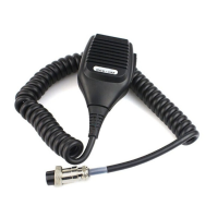
The MIC connector (8 pin) provides input for microphone audio, frequency UP/DWN control, and PTT lines. For USA versions, a touch-tone encoder is integrated into the microphone for autopatch operations, with 16 touch-tone keys. The UP/DWN switches on the microphone allow for momentary or continuous shifting of the displayed frequency and can initiate scan operations when held for about one second. The PTT Switch is used for transmission and also releases scan operations.
The TM-201B is designed for user-friendly operation. The POWER/VOL control serves as both the ON-OFF switch and volume control. Turning it clockwise powers on the unit and increases volume. The SQUELCH control eliminates no-signal noise; it should be adjusted clockwise until the noise disappears (the squelch threshold). This control is also crucial for scan operation, as it defines the point at which the scan will stop.
The display shows the operating frequency in four digits. Indicators such as Scan indicator, VFO B indicator, MR indicator, ALERT indicator, ON AIR indicator, and BUSY indicator provide visual feedback on the transceiver's status. The S & RF meter uses LEDs to indicate incoming signal strength during reception and RF output level during transmission.
The keyboard on the front panel offers dual functions, facilitating memory recall and other operations. The MHz/M3 key shifts the displayed frequency up by 1 MHz and recalls memory channel 3 during memory recall. The A/B key toggles between VFO A and B, restores the VFO frequency after memory recall, and releases scan. The COM (common channel) key recalls the common channel, which can be programmed to any desired frequency.
Verification beep tones provide audible feedback for various operations, such as correct key operation, busy channels during alert, memory scan initiation, and memory storage. The beep level can be adjusted internally.
For mobile installations, the transceiver is equipped with an external speaker connection, allowing for flexible placement. The manual provides detailed instructions for wiring the unit to a car battery, emphasizing correct polarity and fuse protection. It also offers guidance on selecting suitable antenna types for both mobile and fixed station operations, stressing the importance of a low SWR for optimal performance.
The TM-201B is engineered for long-term, dependable operation. The manual provides instructions for cover removal for internal access, which might be necessary for adjustments or repairs.
A Lithium battery is included to retain memory settings even when the transceiver is powered off or disconnected from the power source. This battery typically lasts about five years. If an erroneous display appears due to battery discharge, replacement should be performed by an authorized service facility. Importantly, replacing the battery does not require reprogramming the operating system, only the memory channel information.
A Microcomputer reset function is available. This can be performed by depressing a reset switch through an opening in the bottom cover using a nonconductive rod.
The manual also highlights the TX FINAL MODULE PROTECTION mechanism, which safeguards the final transistor by reducing transmitter drive when reflected power (SWR) is high.
For ordering spare parts, users are advised to specify the model and serial number of the transceiver, schematic number, printed circuit board number, part number, and quantity desired.
In case of warranty service or repair, the manual recommends packing the equipment in its original box and including a detailed description of the problems, along with contact information. It also specifies that a photocopy of the bill of sale or other proof of purchase is required for warranty claims.
The Kenwood TM-201B is a robust and feature-rich 2m FM transceiver, designed for reliable communication with a focus on user convenience and operational flexibility in both mobile and fixed station environments.
| Frequency Range | 144-148 MHz |
|---|---|
| Mode | FM |
| Channels | 200 |
| Weight | 1.2 kg |
| Supply voltage | 13.8V DC |