Do you have a question about the Kenwood TM-221E and is the answer not in the manual?
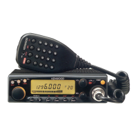
Covers VFO tuning, Power/Volume, Squelch, and TX Offset functions.
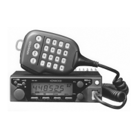
Details keyboard operations for memory, scan, MHz UP, and the COM channel key.
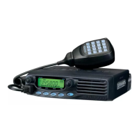
Covers REV, HI/LOW switches, and the display panel indicators like BUSY and S&RF.
Details the keys used for DCS system operation, including ON/OFF and code setting.
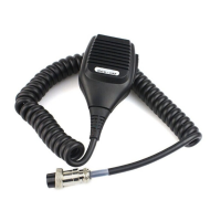
Covers UP/DWN, PTT, and DTMF keys for both microphone versions.
Covers antenna, interconnection, and mounting the transceiver and speaker in a vehicle.
Details speaker installation on a bracket and microphone cable bracket securing.
Covers bracket installation, transceiver mounting, and stacking units for multiple radios.
Covers mobile antenna installation types and power supply connection to the battery.
Covers power supply requirements and antenna selection for fixed station operation.
Steps for receiving signals, transmitting, and key operational precautions.
Instructions for storing frequencies in memory and using scan modes.
Explains Priority Watch (PR.W), Microphone Check, and Oscillating Mechanism functions.
Overview, features, and steps for setting digital access codes.
Setting call signs, precautions, digital squelch, and alert functions.
Instructions for removing covers and adjusting beeper volume.
How to attach/detach mounting boss and remove shaft cover.
Covers battery, microcomputer reset, panel oscillation, scan mode, mic sensitivity, and low power output.
Lists PS-430 Power Supply and Call Sign Display Unit as accessories.
Instructions and installation guide for the optional TU-3A unit.
Covers general info, TX module protection, battery, parts ordering, and service.
| Frequency Range | 144-146 MHz |
|---|---|
| Mode | FM |
| Current drain RX | 0.5 A |
| Impedance | 50 Ω |
| Voltage | 13.8 V |
| Receiver Sensitivity | 0.16 μV (12 dB SINAD) |