Do you have a question about the Kenwood TM-2570A and is the answer not in the manual?
Detailed technical specifications for radio models including frequency, power, and circuitry.
List of accessories supplied with the radio units.
Guidelines for proper installation, ventilation, and power supply requirements.
Instructions for installing the mounting bracket for the transceiver.
Safety precautions, polarity, and fixed station connection guidance.
Vehicle wiring, bonding, and ignition noise suppression methods.
Notes on SWR and antenna connection for mobile use.
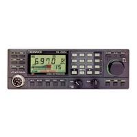
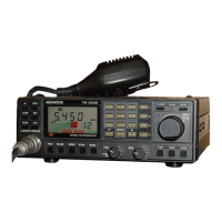
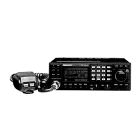
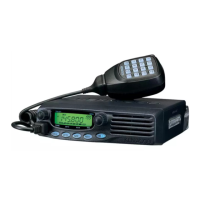
Detailed explanation of the front panel controls, indicators, and their functions.
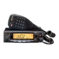
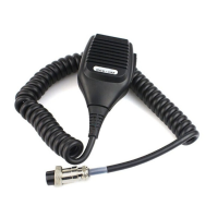
Explanation of microphone controls like UP/DWN and PTT switches.
Guidelines and precautions for transmitting signals and using the HI/LOW switch.
Procedures for backing up, resetting, and inputting memory data.
Instructions for setting up and using paired channels for odd frequency shifts.
Overview of keyboard, memory, and priority channel scan modes.
Procedure to initiate memory scan using keyboard controls.
Procedure to temporarily skip unwanted memory channels during scan.
Information on automatic repeater offset and tone frequency settings.
Pre-programmed repeater offsets and how to override them.
Step-by-step guide to programming telephone numbers into memory.
Procedure to initiate automatic transmission of a stored telephone number.
Explanation of the DCL system's automatic QSY and operating principles.
Step-by-step guide for entering digital access codes.
How to reset the DCL system or return to original frequency.
General info, service procedures, cleaning, and battery replacement.
Information on replacing the microprocessor back-up lithium battery.
Cover removal, power output, and RF power meter adjustments.
Adjustments for microphone gain, DTMF, sidetone, and beeper levels.
Using reset pins, and call sign monitor test pins.
Detailed block diagram of the TM-3530A transceiver's internal components.
Installation procedure for the TU-7 Tone Unit.
Installation procedure for the MU-1 Modem Unit for DCL system.
List of other optional accessories including power supplies.
Description of the SWT-1 antenna tuning unit for efficient transmission.
Guidance on selecting and installing fixed station and mobile antennas.
Types of fixed station antennas and their applications.
Types of VHF mobile antennas and installation considerations.
Methods for reducing noise from ignition and other vehicle sources.
Observing battery capacity and proper connection for mobile operation.
| Brand | Kenwood |
|---|---|
| Model | TM-2570A |
| Category | Transceiver |
| Language | English |