
C
Connie HamiltonJul 27, 2025
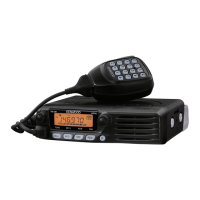
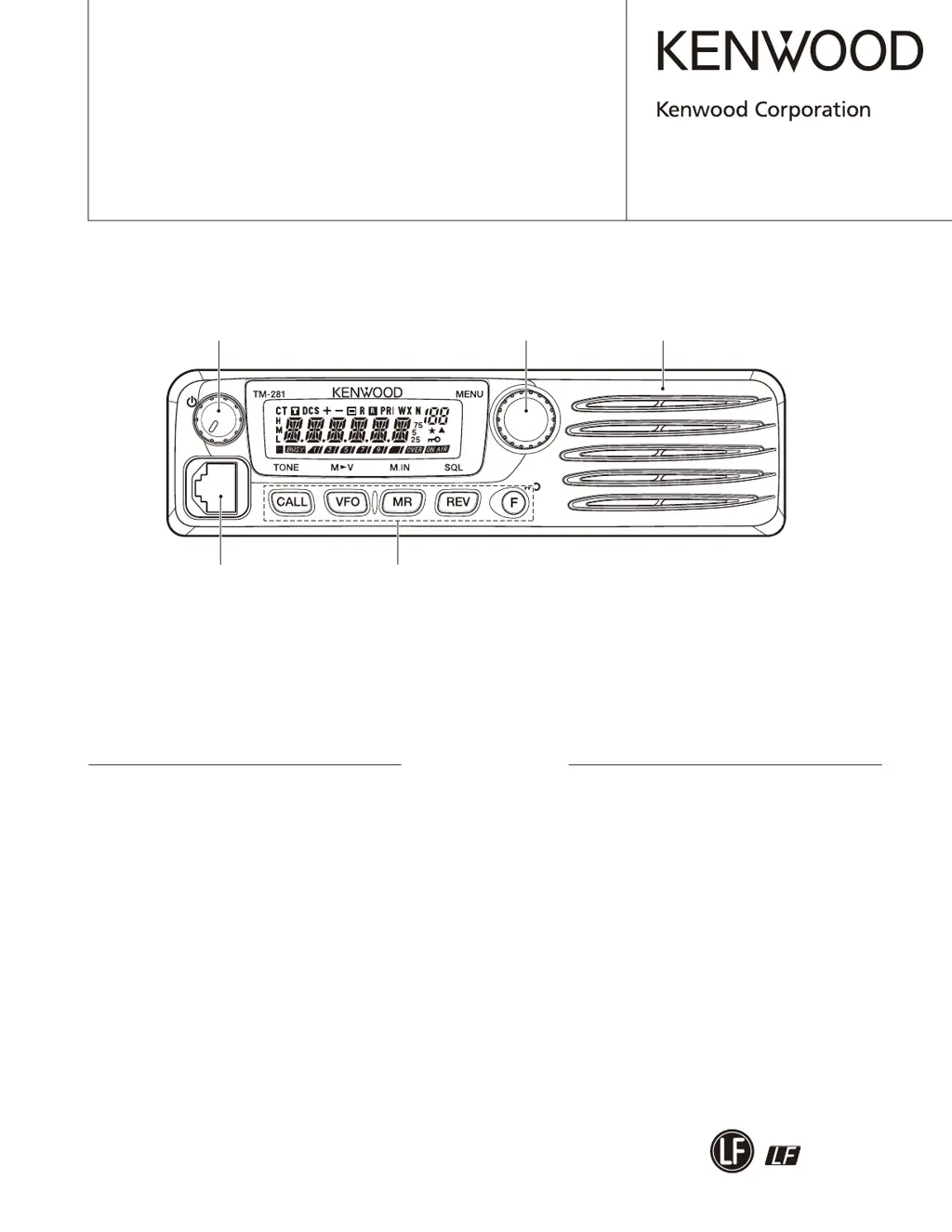
What to do if Kenwood Transceiver won't transmit?
- MMatthew DiazJul 27, 2025
If your Kenwood Transceiver won't transmit when you press the Mic [PTT], first ensure the microphone plug is fully inserted into the front panel connector until the locking tab clicks. If that's not the issue, you may have selected a transmit offset that puts the transmit frequency outside the allowed range. To fix this, press [F], then [MENU], and use the Tuning control to choose Menu No. 5 (SFT). Press [MENU] again and use the Tuning control to select 'OFF'. Store the setting by pressing [MENU], and then press any key (except [MENU]) to exit Menu Mode.