

V
vsullivanJul 26, 2025
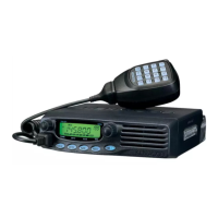
What to do if my Kenwood TM-271A Transceiver won't transmit when I press Mic [PTT]?
- CChristine RichardsJul 26, 2025
If your Kenwood Transceiver won't transmit when you press the Mic [PTT] button, there might be a few reasons: * Ensure the microphone plug is fully inserted into the front panel connector until you hear the locking tab click. Always switch off the power before doing this. * Check if you've selected a transmit offset that's placing your transmit frequency outside the allowed range. To fix this, press [F], then [MENU], and use the Tuning control to go to Menu No. 5 (SFT). Press [MENU] again and use the Tuning control to select “OFF”. Store this setting by pressing [MENU], and then press any key (except [MENU]) to leave Menu Mode. * If you're using an external TNC, make sure it has finished transmitting before you press the Mic[PTT] button.