Do you have a question about the Kenwood TS-520S and is the answer not in the manual?
Covers general operational parameters like frequency range, mode, and components.
Details transmitter output power, suppression, and AF response.
Details receiver sensitivity, selectivity, image ratio, and AF output.
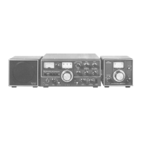
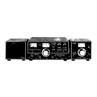
Details the DK-520 option, its features, and DC operation requirements.
Illustrates key transmission audio path circuits including Generator and Carrier.
Depicts RF and IF signal flow, amplification stages, and filtering.
Shows VOX, Noise Blanker, and AVR circuits and their interconnections.
Details VFO, Marker, and Indicator circuits and their signal paths.
Explains the transceiver's double-conversion system and advanced features.
Describes the signal path from microphone to antenna in the transmitter.
Details the signal path from antenna to speaker in the receiver.
Explains the function of the Carrier Unit as a BFO and carrier oscillator.
Details the Generator Unit's role in SSB transmission and DSB signal generation.
Covers RF amplification, ALC system, and control sections within the RF unit.
Describes the IF Unit's role in both transmit and receive signal processing.
Details Noise Blanker and Audio Frequency amplifier circuits.
Explains the functions of the VFO, Marker, and VOX circuit units.
Describes various support circuits like AVR, rectifier, HV, indicator, and final units.
Explains the theory and operation of the speech processor for improved SSB audio.
Details how the speech processor affects audio output levels and quality.
Describes signal characteristics, selectivity, and intermodulation effects.
Explains the antenna connection, RF ATT features, and WWV reception.
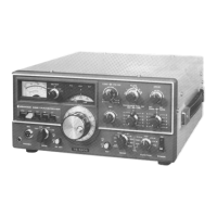
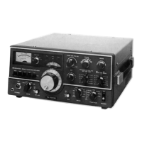
Identifies front panel controls, meters, displays, and knobs.
Shows rear panel connectors, switches, and power inputs.
Shows component placement on the top side of the transceiver chassis.
Shows component placement on the bottom side of the transceiver chassis.
Shows the circuit layout for the VFO Unit (X40-1070-01).
Shows the circuit layout for the Rectifier Unit (X43-1090-02).
Shows circuit layouts for FIX CH. AVR (X43-1100-00) and HV Units (X43-1110-00).
Shows circuit layouts for OSC Coil (X44-1160-00) and ANT Coil Units (X44-1070-00).
Shows circuit layouts for Mixer Coil (X44-1080-00) and Drive Coil Units (X44-1090-00).
Shows the circuit layout for the RF Unit (X44-1200-00).
Shows the circuit layout for the IF Unit (X48-1060-01).
Shows the circuit layout for the AF Unit (X49-0008-01).
Shows circuit layouts for Carrier (X50-0009-01) and Marker Units (X52-0005-01).
Shows circuit layouts for Generator (X52-1090-00) and Indicator Units (X54-1280-00).
Shows circuit layouts for VOX (X54-0001-00) and NB Units (X54-1080-10).
Shows the circuit layout for the Final Unit (X56-1200-00).
Lists capacitor part numbers, types, values, and tolerances.
Lists tubes and semiconductor part numbers and types.
Lists potentiometers, trimmers, and various types of switches.
Lists resistor part numbers, types, values, and tolerances.
Lists coils, speakers, and other miscellaneous components.
Lists parts specific to the VFO and Rectifier units.
Lists parts specific to FIX CH, AVR, and OSC Coil units.
Lists parts specific to Mixer, Drive Coil, and RF units.
Lists parts specific to the IF Unit.
Lists parts specific to Generator and Marker units.
Lists parts specific to NB, VOX, and Indicator units.
Lists parts specific to the Final Unit.
Lists materials used for packing the transceiver and accessories.
Details steps for removing front panel components like glass and knobs.
Details steps for removing the top and bottom covers of the transceiver.
Identifies numbered components located on the subpanel.
Identifies numbered components located on the rear panel.
Details replacement of relays and electrolytic power supply capacitors.
Covers coil pack disassembly and VFO section removal procedures.
Details replacing dial lights, meter lights, meters, and paddle switches.
Describes how to modify the unit for 50W output power.
Addresses no power, no reception, and noise problems during reception.
Troubleshoots carrier, VFO, HET, IF, RF, ANT, and detection circuits.
Troubleshoots S-meter, marker, and WWV reception issues.
Addresses no output, OSC, RF, Generator, FINAL, and IF unit problems.
Troubleshoots meter deflection, ALC, HV, power, and STBY switch issues.
Addresses 9V stabilization and noisy S-meter problems.
Shows required signal generator output levels for receiver adjustment.
Shows measured voltage levels for transmitter adjustment.
Lists necessary equipment for performing adjustments.
Covers initial settings and rear panel adjustments for reception.
Details BPF adjustment for reception and transmission.
Covers Carrier board and Coil pack alignment procedures.
Details adjustments for trap coils, carrier balance, and S-meter.
Covers RIT and calibrator frequency adjustments.
Details VFO frequency calibration steps.
Covers output voltage and final bias current adjustments.
Details Intermediate Frequency Transformer adjustments.
Covers RF meter, power check, and neutralization adjustments.
Covers adjustments for balanced modulator, sidetone, and processor.
Lists technical specifications for the DS-1A DC-DC Converter option.
Shows circuit diagrams for AF, NB, VFO, Carrier, VOX, and Indicator units.
Shows circuit diagrams for IF, FIX CH AVR, HV, and Marker units.
Shows circuit diagrams for RF, Final, and Rectifier units.
| IF Frequencies | 8.83 MHz, 455 kHz |
|---|---|
| Modes | CW, SSB |
| Receiver Sensitivity | 0.5 µV for 10 dB S/N |
| Power Supply | DC 13.8 V |
| Frequency Range | 160-10 meters (including WARC bands) |