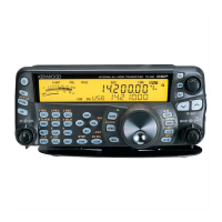
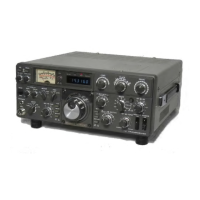
Do you have a question about the Kenwood TS-690S and is the answer not in the manual?
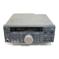
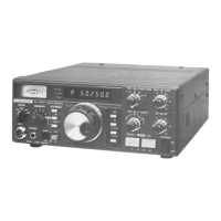
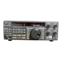
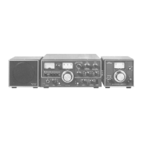
Details the TS-450S/690S series transceiver features and performance characteristics.
Explains the frequency configuration for the TS-690S/450S, covering frequency ranges and modes.
Details the Phase-Locked Loop (PLL) circuit configuration, including frequency dividers and VCOs.
Describes the receiver circuit, covering RF input, IF stages, and signal processing.
Explains the transmitter circuit, including RF output stages, modulation, and power amplification.
Details the digital control unit, including CPU, memory map, and interface diagrams.
Details the terminal connection and block diagram for the TC9174F I/O port expander.
Provides terminal connection and block diagram for the µPD78213GJ-5BJ CPU.
Describes the CXD1225M PLL IC, including block diagram and terminal descriptions.
General parts list for the TS-450S/690S series.
Lists essential test equipment needed for transceiver adjustments.
Procedure for initializing settings and checking the display after power on.
Guides for adjusting PLL and CAR circuits, specifying test points and settings.
Details adjustments for receiver sections like RF Gain, RIT, and IF stages.
Procedures for adjusting transmitter circuits including ALC, power, and bias settings.
Presents the schematic diagram for the PS-33/53 DC power supply.
Describes the circuit operation and features of the TU-8 Tone Unit.
Provides adjustment procedures for the TU-8 Tone Unit.
| Brand | Kenwood |
|---|---|
| Model | TS-690S |
| Category | Transceiver |
| Language | English |