2. BOILER LOCATION
2.1 DIMENSIONS AND MINIMUM
CLEARANCES
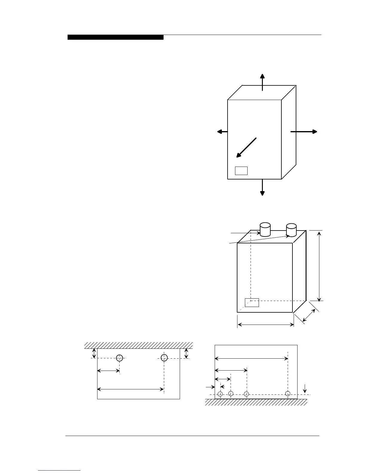
The boiler must be installed in minimum
clearances shown to allow subsequent
servicing, and safe operation. However,
larger clearances may be required
during installation.
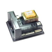
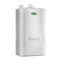
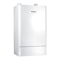
2.2 SERVICE CONNECTIONS
Gas, water, air and flue pipe,
condensation, and electrical connections
are as shown. Gas : 0.75 inch BSP
female. Flow/Return 1 inch BSP female
.
An optional stand-off frame is also
available which mounts behind the boiler
to leave a 50mm deep space behind the
boiler. This is to permit pipe routing
behind the boiler if required. See Section
1.5 - Optional Accessories.
2.3 POSITION
The C45, C40P and C55(P) are not
suitable for external installation. The
boiler may be installed in any room or
internal space, although particular
attention is drawn to the requirements
of the current IEE Wiring Regulations
and, in Scotland, the electrical
provisions of the Building Regulations
applicable in Scotland, with respect to
the installation of the boiler in a room or
internal space containing a bath or
shower.
Where a room-sealed appliance is
installed in a room containing a bath or
shower, any electrical switch or
appliance control, utilising mains
electricity, should be so situated that it
WD536 Chapter 2 - Boiler Location The Keston C45, C40P, C55 & C55P
Installation & Servicing Instructions Page : 7
All dimensions in mm.
150
305 (W hen servicing appliance )
150
Figure 2.1.1
Minimum Clearances
25
25
10 (W hen appliance is operating )