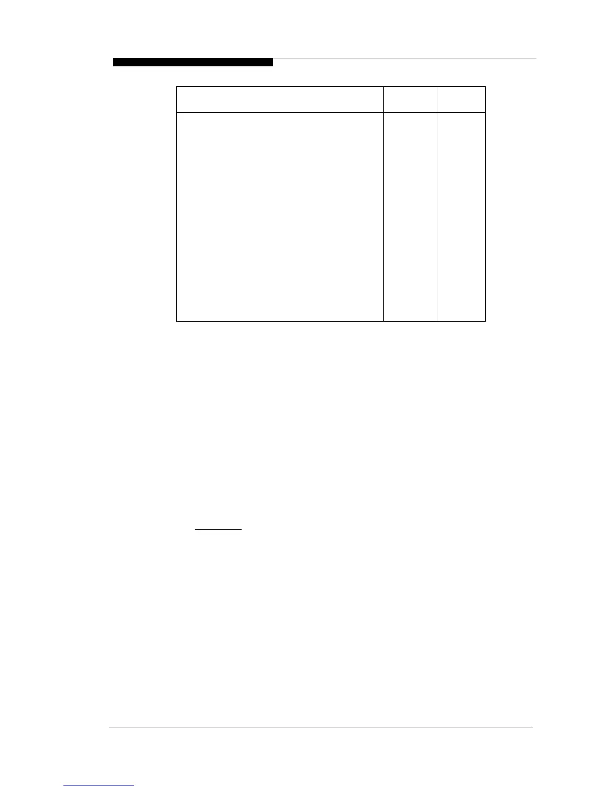
300300L Horizontally from terminal on same wall.
1,5001,500K Vertically from terminal on same wall.
1001,200J From opening in a car port.
1,2001,200I From terminal facing a terminal.
100600H From surface or boundary line facing a
terminal
100200G Above ground or balcony or roof.
50200F From internal or external corner or
boundary lines
5075E From vertical drain or soil pipes.
50200D Below balconies or car port roof.
50200C Below eaves (unventilated)
7575B Below gutters, soil pipes, drain pipes.
50300A Below or beside openable window, air brick,
etc.
Air
Inlet
Flue
Terminal
Dimensions (mm)
Table 2.8.5 Minimum Flue Terminations & Air Inlet Dimensions
2.8.6 Clearances From Wall
Flue outlet and air inlet terminations must be at least 40 mm from the wall face.
2.8.7 Distance Between Flue Outlet & Air Inlet
There is no maximum - the terminations must not be on opposite sides of the
dwelling but can be in areas of unequal pressure
A minimum clearance of at least 300mm must be left between the terminations
and the flue terminal must be directed away from the air intake terminal.
2.8.8 General Installations
All parts of the system must be constructed in accordance with BS 5440 Part 1,
except where specifically mentioned in these instructions.
All pipe work must be adequately supported.
All joints other than push-on or plastic compression connectors must be made
and sealed with solvent cement suitable for muPVC pipes and conforming to BS
6209: 1982.
Consideration must be given to Corgi/Gas Safe bulletin TB200/TB008 regarding
flues in voids.
The boiler casing must always be correctly fitted to the boiler when leaving the
appliance operational.
External wall faces and any internal faces of cavity walls must be made good. For
50mm muPVC terminals, rubber collars are available for flue and air terminals to
finish the external wall face around the terminals (Part No C.08.0.00.07.0)
2.9 AIR SUPPLY
The C45, C40P and C55(P) are room sealed appliances and therefore do not require
purpose provided ventilation to the boiler room for combustion air.
2.10 COMPARTMENT INSTALLATION
The C45, C40P and C55(P) models operate with very low heat emission levels. As a
results the boilers can be installed in a compartment without ventilation.
WD536 Chapter 2 - Boiler Location The Keston C45, C40P, C55 & C55P
Installation & Servicing Instructions Page : 17