11
4
TESTING
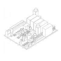
ESQUEMA DEL CONJUNTO 900CT-1A 900CT-1AR
CONEXIONES EN LA CAJA DE TERMINALES
Rele’
spunto
Rele’
com.
Rele’
ch.
Rele’
ap.
Rele’
lamp.
Fus.
6,3a
Fus.
315ma
Modulo radio
Blocco
Mem.
Memoria
Microprocessore
programmato
p.p.
ch.
ap.
foto
fca
fcc
aut.
Rele’
c.a.
+
+
aaaaaaaaaaaaaaaaaa
aaaaaaaaaaaaaaaaaa
aaaaaaaaaaaaaaaaaa
aaaaaaaaaaaaaaaaaa
aaaaaaaaaaaaaaaaaa
aaaaaaaaaaaaaaaaaa
1
2
34
56789
10
11
12
13
14
17 18
t.pausa
T. TRABALHO
Dip switch
di selezione
P pulsante
autoapprendimento
fcc
Comune finecorsa
fca
Trasf.
secondario
Trasf.
primario
autotrasf.
ap.
co.
ch.
50hz
230 vac
lamp.
300mA
24 Vac
Stop
c.a. Max 2w
foto
ch
ap
pp
ped.
com.
ant.
l
n
(motore)
cort.
lamp.
cond.
1-2
3-4
5-6
6-7
8
9
10
11
12
13
14
15-16
17-18
Alimentación de red 230 Vac 50 Mhz.
Salida para intermitente/cortesía (la selección entre intermitente y
cortesía depende de la selección del jumper prefijado) 230Vac
25W máx para intermitente,100 W máx. luz/cortesía.
Salida 24 Vac para alimentación servicios(foto, radio, etc.) Máximo
300 mA.
Salida para testigo portón abierto Vac máx 2W.
Entrada para mando de stop (emergencia, bloqueo o seguridad exterior).
Entrada para dispositivos de seguridad (células fotoeléctricas o
bordes de seguridad).
Entrada para mando de apertura.
Entrada para mando de cierre.
Entrada para funcionamiento cíclico (abre stop cierra stop).
Entrada para mando peatonal (véase Funciones Especiales).
Común para las entradas.
Salida 2º canal (vers.CT-1AS).
Entrada para la antena del receptor de radio.
230VAC
INTERMITENTE
24VAC
TESTIGO C.A.
STOP
CÉLULA
FOTOELÉCTRICA
ABRE
CIERRA
PASO/PASO
PEATONAL
COMÚN
SALIDA 2º CANAL
ANTENA
E
Testing of the entire system where the control unit is installed must be performed by
qualified personnel who must conduct all tests according to the associated risks.
BEFORE POWERING UP THE AUTOMATION
- check all connections
- set all trimmers to minimum
- set all dip switches as required
- set the adjustment trimmer to minimum power
On completion of the above, the unit can be started up.
POWERING UP
- ensure correct operation of all inputs
- adjust the motor output to ensure compliance with current standards
by means of the relative trimmer
- ensure correct direction of motor rotation
- set the work and pause trimmers
- perform the final operation test
MAINTENANCE / DISPOSAL
In the event of malfunctions, ensure exclusively qualified personnel perform
repairs, maintenance or adjustments.
Dispose of all materials in compliance with current regulations.
 Loading...


