11
EN
Following the successful testing of all (and not just some) devices in
the system you can proceed with the commissioning.
You must prepare, and keep for 10 years, the technical le of the
system with the wiring diagram, drawing or photo of the system,
risks analysis and solutions adopted, manufacturer declaration of
conformity of all devices connected, instruction manual of each de-
vice and maintenance schedule of the system.
Fix on the gate or door a plaque indicating the automation data, the
name of the person responsible for the commissioning, the serial
number and year of construction, the CE mark.
Attach a plaque indicating the steps required to manually unlock
the system.
Implement and deliver to the end user the declaration of conform-
ity, the instructions and warnings for use for the end user and the
maintenance schedule of the system.
Make sure the user understands proper automatic, manual and
emergency operation of the automation.
Inform the end user in writing of the dangers and risks still present.
All system components must be tested following the procedures
outlined in the respective instruction manuals.
Check that they meet the guidelines in Chapter 1 - Safety warnings
Check that the gate or door can move freely once the automation
is unlocked, and that they are in equilibrium and stationary if left in
any position.
Check the correct operation of all connected devices (photocells,
sensitive edges, emergency buttons, etc.), testing the opening,
closing and stopping of the gate or door via the connected control
devices (transmitters, buttons, switches).
Carry out measurements of the impact force, as prescribed by
standard EN 12453adjusting the functions of speed, motor force
and deceleration of the unit if the measurements do not give the
desired results until you nd the right setting.
The testing of the system must be performed by qualied techni-
cians who must perform the tests required by relevant legislation
related to risks, ensuring compliance with the provisions of the
regulations, in particular the EN 12453standard, which species the
testing methods for the automation of doors and gates.
5 - TESTING AND COMMISSIONING THE AUTOMATION SYSTEM
Open entirely the gate.
Put a rack element on the pinion gear and fasten it to the gate with
screw and spacing bars (Fig.10).
Move the gate manually bringing the pinion gear into line with the
last spacing bar.
Fasten the rack element for good.
The stop lock position must assure that the limit switch brackets
don’t collide with the pinion gear. (Fig.11)
For a correct positioning of the other elements and to assure their
straightness, it is necessary to employ a rack element using it as
support and reference. It is besides necessary to assure an aperture
of 2 mm between rack and pinion gear, so that the gate weight doe-
sn’t rest on the gearmotor pinion gear.
ATTENTION !
The gate has to be equipped with stop locks at the opening and
closing, which prevent the gate derailment.
Haul the gate manually at the opening leaving, depending on the
gate weight, a crack from 30 to 50 mm between the main gate and
mechanical stop.
Fasten the limit switch bracket through the dowels so that the limit
switch is pressed (Fig.11).
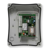
Follow the instructions of the control panel and close the cover.
4.5 - Rack assembling
4.6 - Limit switch xing
5.1 - Testing
5.2 - Commissioning