4 5
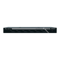
Serial IR, RS-232, and TCP/IP Control
The KD-4x4CSA/KD-8x8CSA features a 6-Pin Terminal Block for IR and RS-232 Control. Signals
may be received from these connections as well as the Ethernet Jack for TCP/IP Control. Serial
commands may be found in the “Communications Protocol” section.
For Serial IR, connect a mono cable to the Multi-function I/O port on the Master Controller or
the IR Extender/IR Connecting Block of the 3rd party control system. The other end would then
connect to Pins 1 and 2 on the 6-Pin Terminal Block. IR In is Pin 1; Ground is Pin 2.
For Serial RS-232, connect a stereo cable to the Multi-function I/O port on the Compass Control
Master Controller or the RS-232 port of the 3rd party control system. The other end would then
connect to Pins 3,4,5,6 on the 6-Pin Terminal Block. Tx Data is Pin 3; Rx Data is Pin 5; Ground is
Pin 4 and/or Pin 6. Either ground pin may be used for RS-232.
For TCP/IP control, connect an Ethernet cable from the KD-4x4CSA/KD-8x8CSA to a network
router or connect a crossover cable from the KD-4x4CSA/KD-8x8CSA directly to a PC.
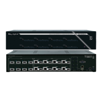
Connections, Buttons and LEDs
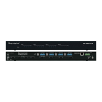
Rear Panel Connections:
All connections to the KD-4x4CSA/KD-8x8CSA are found on the rear panel of the units.
Refer to the illustrations below for port assignments while making connections.
HDMI Inputs & LEDs HDMI Outputs & LEDs
Serial IR
& RS-232
TCP/IP
Power
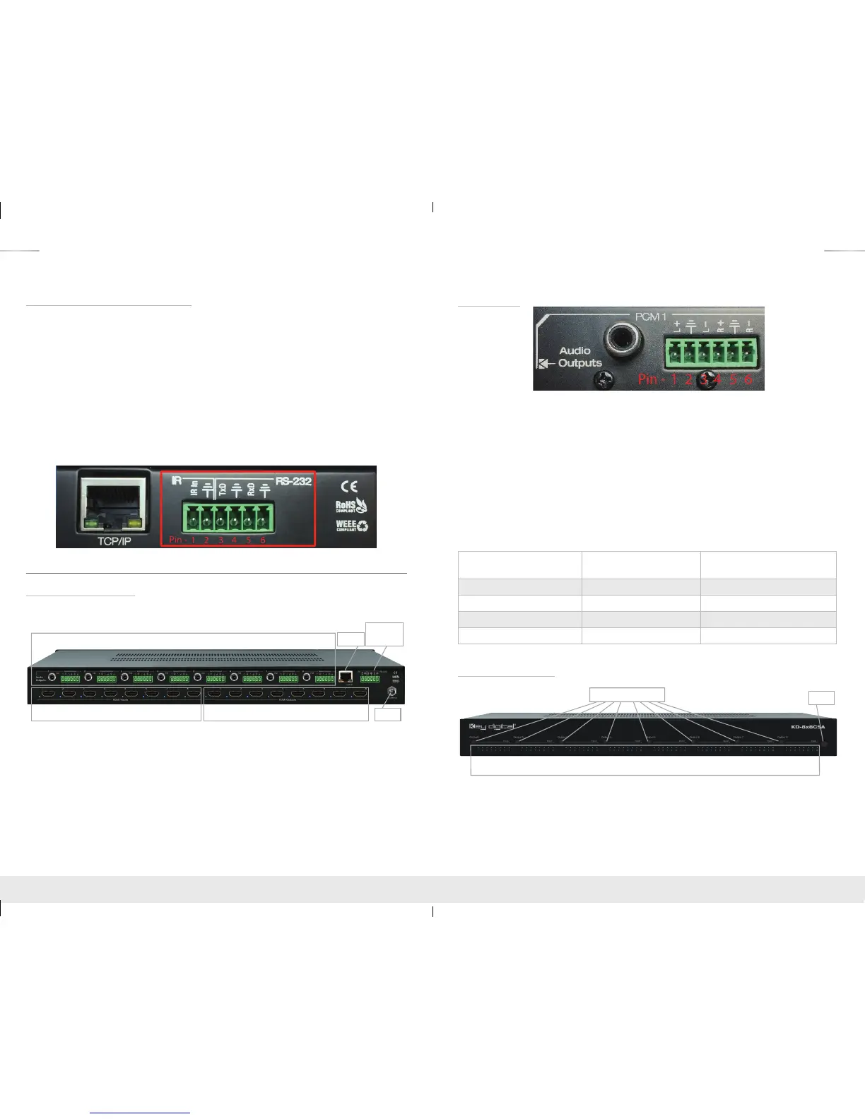
Audio Outputs - PCM and 6-Pin Terminal Block
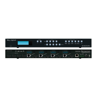
› HDMI Inputs:
» The HDMI Inputs are located on the bottom left side of the back panel. The Inputs have a
blue LED that will illuminate solid during active link (voltage + data link)
› HDMI Outputs:
» The HDMI Outputs are located on the bottom right side of the back panel. The Outputs
have a blue LED that will illuminate solid during active link (voltage + data link)
› Ethernet Jack, Serial IR, RS-232, and Power Block:
» Located on the right side of the back panel.
Audio Outputs
› Each Output Channel has 1 Analog L/R Balanced/Unbalanced connection: 6-Pin Terminal Block
which provides de-embedded 2ch Balanced Analog Audio Output from selected HDMI input
source
› The Pin assignment for the audio is as follows:
» Left + is Pin 1; Left - is Pin 3; Left Ground is Pin 2.
» Right + is Pin 4; Right - is Pin 6; Right Ground is Pin 5.
› Each Output Channel has 1 Digital Audio Output: RCA Jack which provides de-embedded
Digital Audio Output from selected HDMI input
› There are no volume or tone control features, only muting control of the external audio outputs
via RS232 and TCP/IP
› There are no DSP features. Audio must be configured in the source. For example, in order to
achieve 2ch analog audio output, the selected HDMI input source audio format must be 2ch.
Audio Input
Signal Format
Audio L/R
Output
Digital Audio Output
(Coax and Optical)
2ch PCM Pass-Through Pass-Though
Multi-Channel PCM MUTE MUTE
Dolby DTS MUTE Pass-Though
HD Audio MUTE MUTE
Front Panel Operation
IR Eye
Input LEDs
Output Select Buttons
› There are 4/8 Output buttons along the front panel.
› Pressing an output button will select the next HDMI input.
› A blue LED will indicate which Input has been selected for each Output.
› Front button control can be disabled/enabled via serial control if desired.
› The Optical IR window is located on the right side of the front panel receives IR remote control
signals.
KD-4x4_8x8CSA_Manual.indd 4-5 8/4/16 10:30 AM