2
E GS (Lock) IM
This device complies with part 15 of FCC Rules and Innovation, Science and
Economic Development Canada's licence-exempt RSSs. Operation is subject
to the following two conditions: (1) this device may not cause harmful
interference, and (2) this device must accept any interference received,
including interference that may cause undesired operation.
Le présent appareil est conforme à la partie 15 des règles de la FCC et aux
normes des CNR d’Innovation, Sciences et Développement économique
Canada applicables aux appareils radio exempts de licence. L’exploitation
est autorisée aux deux conditions suivantes : (1)l’appareil ne doit pas
produire de brouillage, et (2) l’appareil doit accepter tout brouillage subi,
même si le brouillage est susceptible d’en compromettre le fonctionnement.
FCC CAUTION
Changes or modifications not expressly approved by the party responsible
for compliance could void the user’s authority to operate the equipment.
Note: This equipment has been tested and found to comply with the limits for
a Class A digital device, pursuant to part 15 of the FCC Rules. These limits
are designed to provide reasonable protection against harmful interference
when the equipment is operated in a commercial environment. This
equipment generates, uses, and can radiate radio frequency energy and, if
not installed and used in accordance with the instruction manual, may cause
harmful interference to radio communications. Operation of this equipment in
a residential area is likely to cause harmful interference in which case the user
will be required to correct the interference at his own expense.
Chapter 1 Before Operation
1-1 Overview and Configuration
The GS (Lock) is a Type4 Interlocking Device with guard lock based on
ISO14119.
Coding level: Low or high (switchable)
“4-7 Coding Level” (page 7)
By combining the GS (Lock) with a door or similar movable safety guard and
with a safety-related control system, it is possible to prevent the door or
similar part from opening during hazardous machine operations.
The GS (Lock) can also be used for other purposes such as
protecting manufacturing processes.
1-2 Product List
Main unit
For details on the main unit models, see “5-1 Model Number Description”
(page 7).
M12 connector type cables
z Standard cables
Use this cable in combination with a main unit (connector type) or
extension cable.
z Extension cables
Mounting brackets
z For main unit and actuator set
GS-B21
z For actuator
GS-B31, GS-B33, GS-B41, GS-B43
Optional parts
z Replacement actuator
GS-A21
1-3 Package Contents
Main unit
• Sensor (main unit)
• Actuator
• Instruction Manual
Chapter 2 Installation
2-1 Installation Conditions
Note the following items before installation.
The effect of surrounding metal
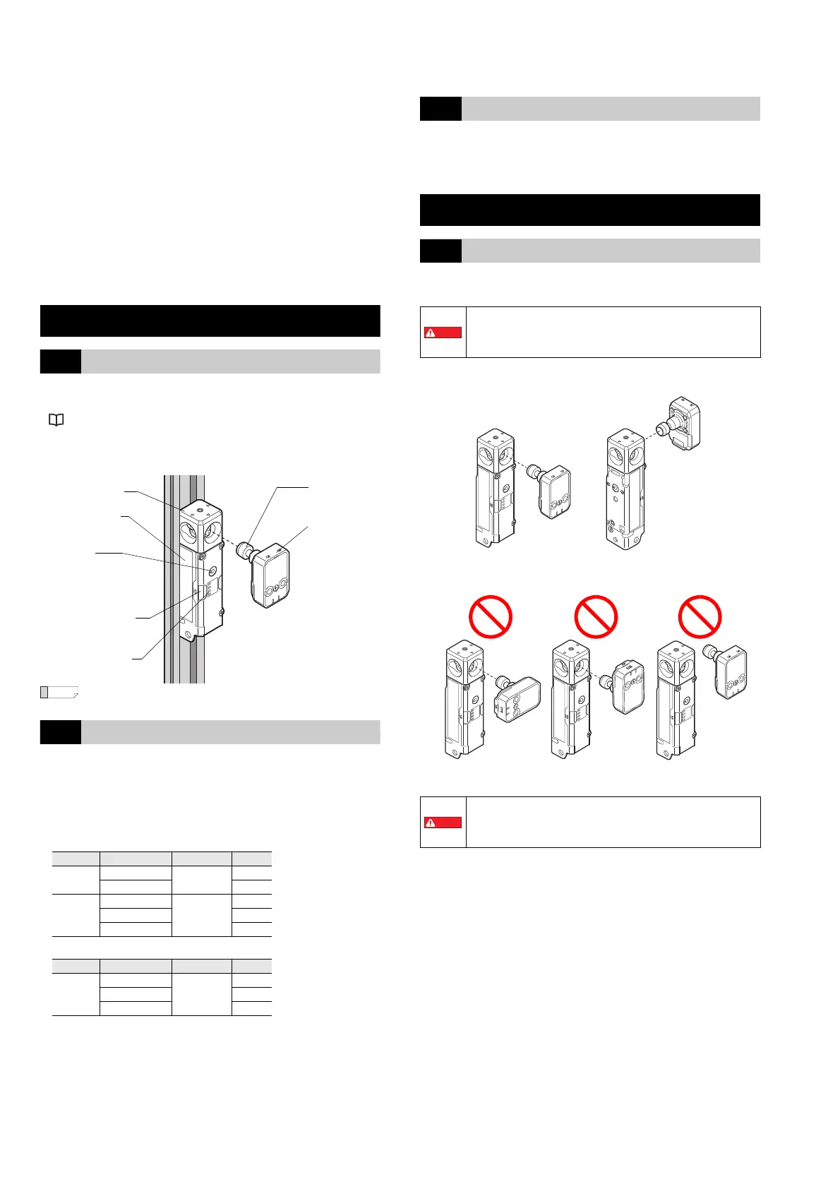
Sensor and actuator orientation
Correct installation orientations
Incorrect installation orientations
Type Model
Number of pins
Length
Standard
GS-P8C5
8
5 m
GS-P8C10 10 m
Advanced
function
GS-P12C5
12
5 m
GS-P12C10 10 m
GS-P12C20 20 m
Type Model
Number of pins
Length
Standard
GS-P8CC1
8
1 m
GS-P8CC5 5 m
GS-P8CC10 10 m
Lock bolt
Highly visible indicator
Center indicators
Actuator
Main unit
Auxiliary
release
mechanism
Metal head
The sensor’s operating distance may be affected by the
presence of metal in the surrounding area. After installation,
determine the minimum safety distance based on the actual
operating distance and check if it is provided appropriately.
• Install the GS (lock) so that the lock bolt inserts securely
into the sensor’s insertion slot when the door or similar
object to which the actuator is installed is closed.
• Do not use the GS (Lock) as a mechanical stopper.
From the front
From the side
Horizontal
Not inserted in
the insertion slot
Reverse
 Loading...