6
E GS (Lock) IM
z Power-to-lock type
In lock link mode (initial setting):
• The sensor has detected an actuator.
• Lock control input is ON.
• Safety inputs are ON.
• The lock bolt is inserted in the insertion slot of the main unit correctly.
In open/close link mode:
• The sensor has detected an actuator.
• Safety inputs are ON.
*1: The OSSDs keep OFF state in the interlock reset ready state.
OSSD operation switching
The OSSDs operation can be switched on the advanced function, Power-to-
lock type. The OSSDs operation is determined by the wiring of the OSSD
operation switching input during startup.
• Lock link mode: Links the OSSDs with the lock operation.
OSSD operation switching input 1: Open
• Open/close link mode: Links the OSSDs with the open/close operation of
the door or similar object.
OSSD operation switching input 1: Connected to 0 V
OSSD operation switching input 2: Connected to 24 V
4-2 Safety Input
This function controls the OSSDs of the GS (Lock) with input signals from
sensors or similar devices connected to the safety inputs.
Safety input 1 and safety input 2 form a safety input pair. If safety input 1 or
safety input 2 goes to OFF state, the OSSDs go to OFF state.
Multiple GS units can be connected and used in an expanded system (with a
cascade connection) by connecting the OSSDs of a different GS (Lock) or GS
(Non-contact) to the safety inputs. The system can be expanded to include
up to twenty five units in the case of the GS (Lock). For details, see
“Cable length and number of connected units” (page 5).
• Wire the safety inputs as shown below when they are not in use.
PNP type: Short circuit to 24 V.
NPN type: Short circuit to 0 V.
• If safety input 1 and safety input 2 are mismatched for 3
seconds or more a Safety Input Error will occur.
Emergency stop switch/button wiring
Wiring an emergency stop switch/button to the safety inputs makes it
possible to perform an emergency stop on the machine by pressing the
emergency stop switch/button.
4-3 Lock Function
The lock function makes it possible to keep closed the door or similar item to
which the GS (Lock) actuator is installed by maintaining a physical
connection between the type and actuator.
The operation of the lock function varies depending on the model of the GS
(Lock) main unit (Power-to-release type, Power-to-lock type).
On the advanced function, Power-to-release type, lock control input 1 and
lock control input 2 operate as a lock control input pair.
Power-to-release type lock function
<Lock operation>
On the Power-to-release type, the lock activates immediately when the
actuator is detected.
<Lock release operation>
On the Power-to-release type, setting the lock control input(s) to ON releases
the lock.
The lock can also be released manually by using the auxiliary release on the
front or back of the unit. For details, see “Auxiliary release” (page 6).
Power-to-lock type lock function
<Lock operation>
On the Power-to-lock type, the lock activates when the lock control input turns
ON with the actuator already detected.
<Lock release operation>
On the Power-to-lock type, setting the lock control input to OFF or interrupting
the power supply of the GS (Lock) releases the lock.
The lock can also be released manually by using the auxiliary release on the
front or back of the unit.
For details, see “Auxiliary release” (page 6).
Auxiliary release
This is a mechanism for manually releasing the lock of the GS (Lock). Use it to
manually release the lock in situations where the type malfunctions.
The auxiliary release mechanism has two states.
Normal state: The lock can be applied by way of lock control input(s).
Released state: The lock cannot be applied regardless of the state of the
lock control input(s).
The lock operation will not be executed even in states in
which it is possible.
• A separate auxiliary release key is required in order to
switch between the normal and released states. A hex key
with an across-flats size of 3 mm (M4 size) can be used as
the auxiliary release key.
• Provide the protection on the auxiliary release mechanism
to prevent unintended actuation (e.g. protected by seal with
security screw paint).
• With the auxiliary release mechanism set to the released
state, the lock will not be applied even when the door is
closed. After using the auxiliary release, return the auxiliary
release mechanism to the normal state and seal it again
prior to normal use.
• For the wiring to a safety-related machine control system,
the output of both OSSD 1 and OSSD 2 must be used by the
safety-related machine control system in order to create a
safety system.
• If only one OSSD output is used to construct the machine’s
control system, an OSSD malfunction will make it
impossible to stop the machine, which may lead to
extremely dangerous situations including serious injury to
or death of the machine’s user.
• When using a PNP type, do not cause a short-circuit
between the OSSD and +24V. Otherwise, the OSSDs will
stay in the ON-state and it will cause a dangerous situation.
• When using a PNP type, be sure to connect the load
between the OSSD and 0 V. Connecting this between the
OSSD and +24 V by mistake will invert the OSSD operation
from its normal behavior, which is extremely dangerous.
• When using an NPN type, do not cause a short-circuit
between the OSSDs and 0V. Otherwise, the OSSDs stay in
the ON-state and it will cause a dangerous situation.
• When using an NPN type, be sure to connect the load
between the OSSD and +24 V. Connecting this between the
OSSD and 0 V by mistake will invert the OSSD operation
from its normal behavior, which is extremely dangerous.
• To prevent malfunctions caused by ground faults on the
OSSD output wire, perform wiring in a manner such that the
requirements specified in paragraph 9.4.3 of IEC 60204-1
are met.
• Use an emergency stop switch/button that has two or more
independent, NC (normally closed) contacts. For the
requirements related to emergency stop switches/buttons,
see IEC 60204-1, ISO 13850, and all other requirements,
regulations, standards, and laws related to occupational
safety and health in the country or area where the GS (Lock)
will be used. For such regulations, you should directly
contact the regulatory agency responsible for occupational
safety and health in your country or region.
• Ensure that the device does not start or restart automatically
when the emergency stop switch/button is reset.
• Only the devices shown below can be connected to the
safety inputs. Do not connect any other devices.
•
GS (Lock) OSSDs, GS (Non-contact) OSSDs, and emergency
stop switch/button
• When using a PNP sensor, please connect the OSSDs of the
PNP type GS (Lock) or GS (Non-contact) to the safety
inputs.
• When using a NPN sensor, plesae connect the OSSDs of the
NPN type GS (Lock) or GS (Non-contact) to the safety
inputs.
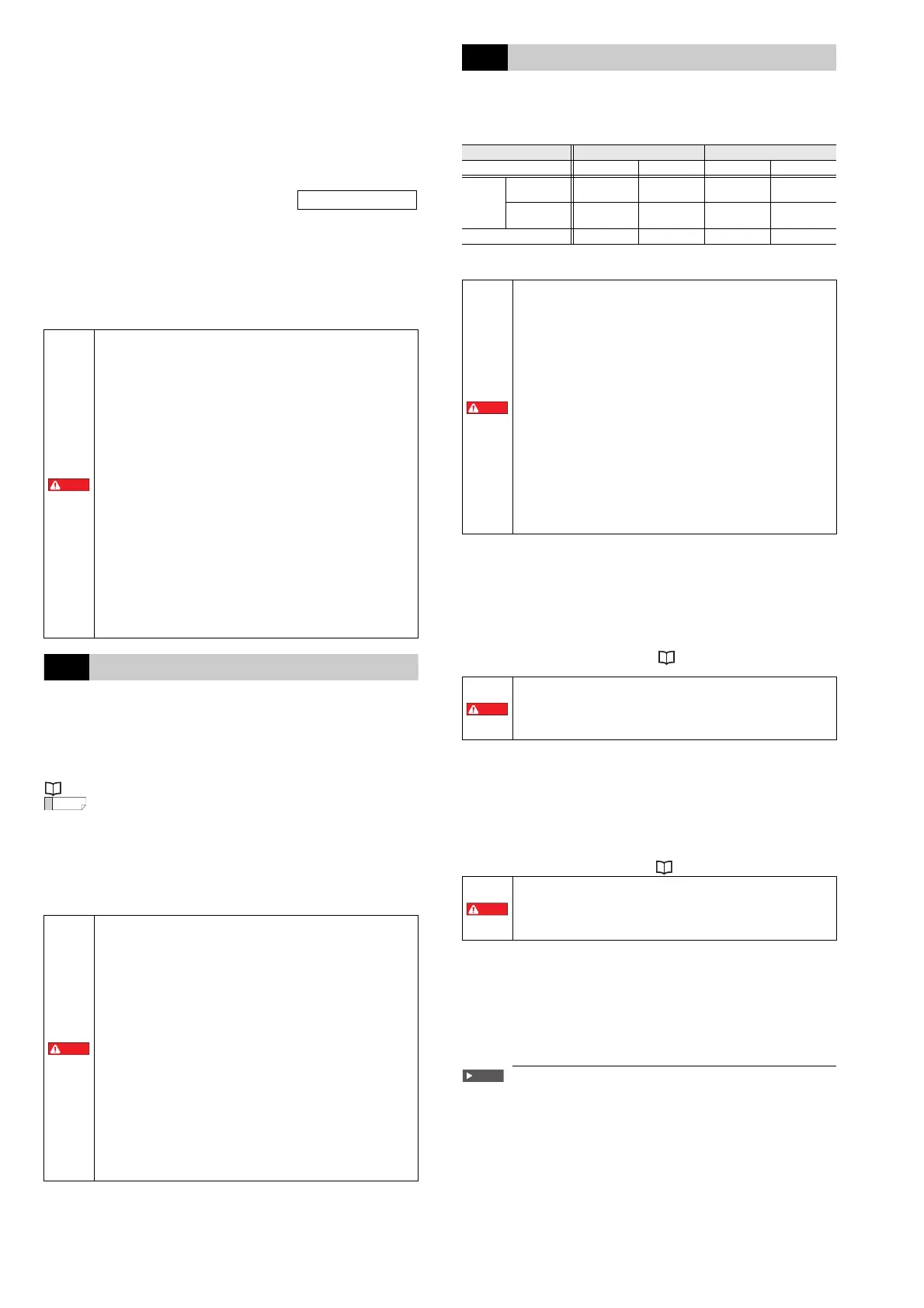
Type Power-to-release type Power-to-lock type
Actuator detection status Not detected Detected Not detected Detected
Power
ON
Lock Control
Input ON
Lock released Lock released Lock on close Locked
Lock Control
Input OFF
Lock on close Locked Lock released Lock released
Power OFF Lock on close Locked Lock released Lock released
•
When using the lock function for a safety-related control
system to achieve PLe, be sure to wire both lock control
inputs (lock control input 1 and lock control input 2) to the
machine’s control system in order to construct a safety
system.
•
The GS (Lock) does not monitor between lock control inputs
for short circuits. When using the two lock control inputs to
achieve PLe, use a safety PLC or some other such device that
can detect short circuits on outputs.
•
When using only one lock control input for the machine’s
control system, the lock control input malfunctioning will
make it impossible to perform locking.
•
When using a PNP type, do not cause a short-circuit between
the lock control input and +24 V. Doing so will make the lock
control input ON at all times, which may be dangerous.
•
When using an NPN type, do not cause a short-circuit between
the lock control input and 0 V. Doing so will make the lock
control input ON at all times, which may be dangerous.
•
To prevent malfunctions caused by ground faults on the lock
control input wire, perform wiring in a manner such that the
requirements specified in paragraph 9.4.3 of IEC 60204-1 are
met.
• If the power supply of the GS (Lock) main unit is
interrupted, the door will be locked, so it is possible for
people to be trapped within the chamber.
• Check that the machine has stopped, and then release the
lock.
Do not use the Power-to-lock type lock function with a safety-
related control system. The lock is released when the power
supply of the GS (Lock) is interrupted, so operators may be
exposed to dangerous situations depending on the operating
status of the machine.
 Loading...