4
E GS (Lock) IM
3
4
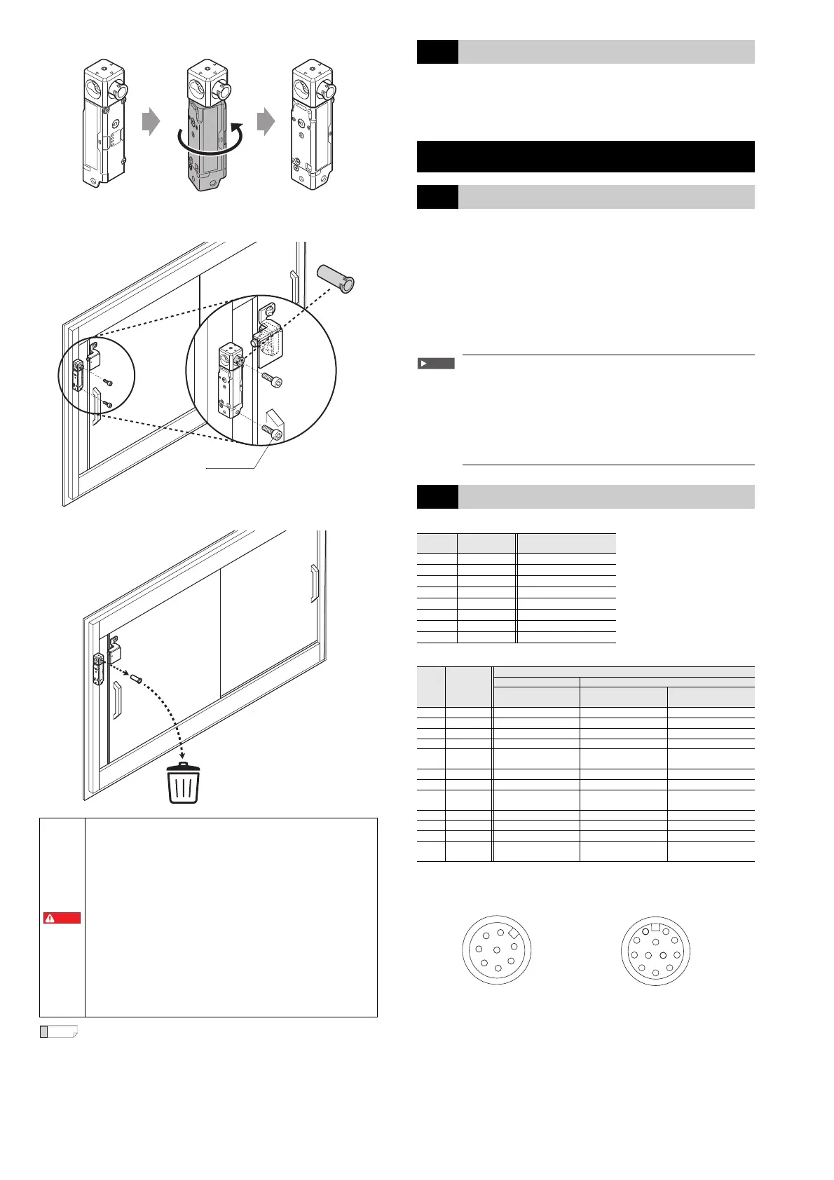
To support the installation of screw, a plastic pipe is pre-inserted to the
insertion slot in the metal head. Insert a screw into this pipe to smoothly set
the screw in appropriate position.
5
• When replacing the sensor or actuator, do so by following the
same procedure.
• The appropriate screws to mount the main unit and the bracket
must be purchased separately.
2-3 Cascade Connection Between Units
Multiple GS (Lock) and GS (Non-contact) units can be connected in series (in
a cascade connection).
This makes it possible to monitor the opening and closing of multiple doors or
similar items on the same machine.
For the wiring method, see "Cascade connection wiring example".
Chapter 3 Wiring
3-1 Power Supply
If the power supply for the GS (Lock) is the converting type, the power supply
for the GS (Lock) must meet the conditions listed below in order to meet the
requirements specified in ISO 14119, IEC 60947-5-3, UL 61010-1, and CAN/
CSA-C22.2 No. 61010-1.
(a) The rated output voltage is within 24 V DC ±20 % (Ripple P-P 10 % or
less, Class2, SELV, Overvoltage category II).
(b) The insulation between the primary and secondary circuits is reinforced or
double insulation.
(c) The power supply complies with the laws, regulations, and standards
related to items such as electrical safety and electromagnetic
compatibility (EMC) in the country or area in which the GS (Lock) will be
used.
When the power supply used with the GS (Lock) is shared
with other machines or electrical products, the voltage
supplied to the GS (Lock) may drop due to temporary
increases in the current consumption of these other machines
and the GS (Lock) may also be affected by the noise
generated by these other machines. Errors or other such
problems may occur with the GS (Lock) in this situation, so it
is strongly recommended to avoid sharing the power supply
of the GS (Lock) with other machines or electrical products.
3-2 Cable Wire Colors and Functions
Standard type (loose wires or M12 connector, 8 pins)
Advanced function type (M12 connector, 12 pins)
Pin layout (Main unit, M12 connector type)
• To minimize defeat possibilities, GS (Lock) should be
installed in a position where the accessibility to GS (Lock)
is prevented (e.g. mounting out of reach, physical
obstruction or shielding or mounting in hidden position),
otherwise use non-detachable fixing to prevent dismantling
or de-positioning of GS (Lock) (e.g. Using a flat head screw
and plugging the slot on the screw head with a high-
strength threadlocker after tightening the screw or other
equivalent fixing system).
Refer ISO 14119 for more information to minimize defeat
possibilities.
• Securely tighten the screws for the sensor, actuator, and
mounting brackets according to the specified tightening
torques.
• To prevent self-loosening, use screw locker on the screws
fixing the GS (Lock).
• If the dedicated bracket is not appropriate, please contact
nearest KEYENCE office.
M5 screws
Tightening torque: 3.0 N⋅m
Strength class:
Carbon or alloy steel: Property class 8.8 or higher
Stainless steel: Property class **-70 or higher
Plastic pipe
Pin
number
Wire color Function
1 Gray AUX output
2 Brown +24 V
3 Light blue Lock control input
4 Red/white Safety input 2
5 Black OSSD1
6 White OSSD2
7Blue 0 V
8 Red/black Safety input 1
Pin
number
Wire color
Function
Power-to-release Power-to-lock
– Lock link mode
Open/close link
mode
1 Brown +24 V +24 V +24 V
2 Red/black Safety input 1 Safety input 1 Safety input 1
3 Blue 0 V 0 V 0 V
4 Black OSSD1 OSSD1 OSSD1
5 Gray AUX output 1 AUX output 1
OSSD operation
switching input 2
6 Red/white Safety input 2 Safety input 2 Safety input 2
7 White OSSD2 OSSD2 OSSD2
8Pink
Interlock/
EDM selection input
Interlock/
EDM selection input
Interlock/
EDM selection input
9 Gray/black AUX output 2 AUX output 2 AUX output 2
10 Light blue Lock control input 1 Lock control input 1 Lock control input 1
11 Yellow Reset/EDM input Reset/EDM input Reset/EDM input
12
Light blue/
black
Lock control input 2
OSSD operation
switching input 1
OSSD operation
switching input 1
Standard type
(M12, 8 pins, male)
Advanced function type
(M12, 12 pins, male)
 Loading...