4
GV-IM-E
Detection method
The GV Series has two type of detection methods: "Distance detection method" and
"Reference surface (DATUM) detection method".
The reference surface (DATUM) detection method can only be used when
performing reference surface calibration.
Control output 2 is fixed to distance detection method for all operation modes.
Distance detection method (Normal)
Detects the distance between the detection target and the sensor head, and
then performs control output. The following table shows each operation mode
and the auto calibration that can be used.
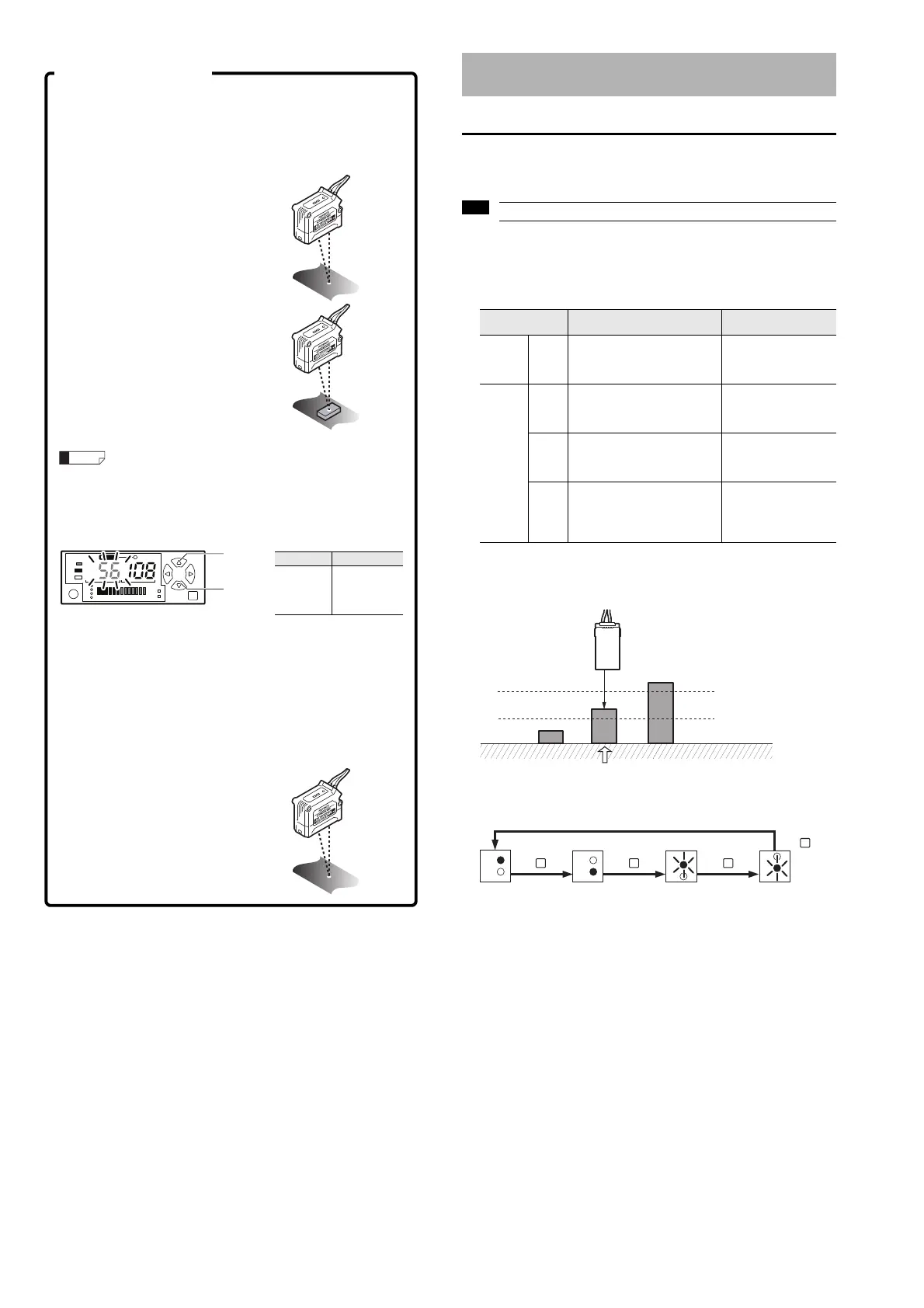
z Area detection mode (F-2 mode)
Operation image
When using the F-2 mode, the channel No. indicator switches in the following
order each time the [MODE] button is pressed.
Configure the sensitivity setting in F-1 mode (with the default settings).
2-point calibration
The setting is automatically calculated as the mean value detected from two
points: with the workpiece and without the workpiece.
1 Press the [SET] button once
without a workpiece in place.
The current value without the
workpiece is read.
2 Place a workpiece in the
detection position, and quickly
press the [SET] button once
again.
This concludes 2-point calibration
and the sensor returns to the
detection state.
If there is very little difference between the values obtained in
Step 1 and Step 2, then "---" flashes in the setting value display
area after calibration is complete. The setting value is still
updated.
Fine-tune setting value
Use the [Up] and [Down] arrow buttons to fine-tune the setting value.
Reference surface (DATUM) calibration
Use DATUM calibration when comparator output cannot be performed
correctly during 2-point calibration (due to problems such as chattering from
the surface of the workpiece).
3 Press the [SET] button once without a workpiece in place
(reference surface).
4 Using the same conditions,
Item Setting range
Setting
value
fine-
tuning
-199 to 999
Increases
the setting
value
Decreases
the setting
value
Configuring the Sensitivity Setting and
Operation Mode
Operation mode Description
Usable
auto calibration
General F-1
Normal detection mode
The most general mode.
ON/OFF judgment is performed
based on one setting value.
2-point calibration
Full auto calibration
Maximum sensitivity
setting
Special
F-2
Area detection mode
On/OFF judgment is performed
on an area based on two
settings.
2-point area calibration
1-point area calibration
A-1
Edge hold mode
Detects the change in distance
(derivation) to the target and
holds the display.
2-point calibration
Full auto calibration
Maximum sensitivity
setting
A-2
Surface detection mode
When multiple beams of light are
reflected from the detection
target, the closest reflected light
is judged as the detection value.
2-point calibration
Full auto calibration
Maximum sensitivity
setting
OFF
OFF
ON
LOW setting value
HIGH setting value
Only this will turn ON.
1
2
1
2
1
2
1
2
MODE
Press once.
MODE
Press once.
MODE
Press once.
MODE
Press once.
Control output 1
(black) HIGH setting
value
• Channel No. 1
indicator lights up
Control output 1
(black) LOW setting
value
• Channel No. 2
indicator lights up
Control output 2
(white) HIGH setting
value
• Channel No. 1
indicator flashes
Control output 2
(white) LOW setting
value
• Channel No. 2
indicator flashes