Do you have a question about the Keysight Technologies 34950A and is the answer not in the manual?
Highlights important safety warnings and cautions for instrument use.
Details rights for U.S. government use of commercial software and data.
Describes the warranty terms and disclaims implied warranties.
General safety precautions to be observed during all phases of operation.
Precautions regarding applying power and grounding the instrument.
Warning against operating the instrument in explosive atmospheres.
Information regarding compliance with the Waste Electrical and Electronic Equipment Directive.
Contact information and web links for sales and technical assistance.
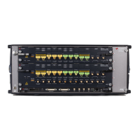
Overview of the 34950A module's capabilities and features.
Defines the numbering and assignment of digital channels and counter/totalizer channels.
Details the electrical specifications for the digital I/O lines.
Provides guidance on environmental and operating conditions for the module.
Defines channel numbering and how width affects operations.
Explains how to read digital data using SCPI commands.
Details SCPI commands for writing digital data to channels.
Configures channel width, polarity, threshold, level, and drive modes.
Configures handshake lines' input threshold, output drive, and polarity.
Details synchronous handshake for unbuffered and buffered operations.
Details synchronous handshake for unbuffered input operations.
Details synchronous handshake for unbuffered output operations.
Explains downloading and outputting traces from memory.
Details capturing and retrieving data into memory.
Procedures for removing traces from memory to free space.
Configures interrupt lines to control memory output operations.
Sets interrupt lines for pattern match or memory fill events.
Default mode for counters; automatically starts running and counts events.
Mode for frequency, period, duty cycle, and pulse width measurements.
Sets input and external gate threshold voltages for counter channels.
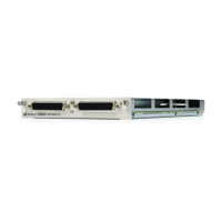
Details the D-sub connectors and their pin assignments.
Details pin assignments for the P1 connector (Bank 1).
Details pin assignments for the P2 connector (Bank 2).
Describes the optional terminal block with screw type connections.
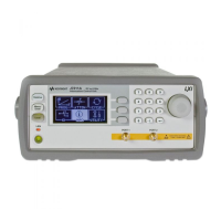
| Type | Control Unit |
|---|---|
| Operating Temperature | 0 to 50 °C |
| Storage Temperature | -40 to 70 °C |
| Number of Slots | 3 |
| Measurement Types | DC Voltage, DC Current, Resistance, Temperature, Frequency, Capacitance |
| Communication Interfaces | USB, GPIB |
| Power Supply | 100 to 240 VAC, 50/60 Hz |
| Supported Modules | 34901A, 34902A, 34903A, 34904A, 34905A, 34907A, 34908A |