Keysight 34950A User’s Guide 19
Synchronous Handshake Mode
In the synchronous handshake mode, a strobe or clock signal is used to transfer
data to or from an external device. The strobe line (H1) is an output and is pulsed
once for each transfer.
Synchronous Unbuffered Inputs
For synchronous handshake unbuffered inputs the H0 line indicates the direction
of the transfer. This line is set high to indicate an input operation. The H0 line will
remain in the high state until the 34950A direction is changed. The H1 line is the
strobe output line. The H2 line is not used and is set to high impedance.
The timing of the input operation is controlled by the T
CYCLE
parameter set using
the CONFigure:DIGital:HANDshake:RATE command. This setting affects
strobe width, memory clock rate, as well as the setup and hold times. Alternatively,
the reciprocal form of the command CONFigure:DIGital:HANDshake:CTIMe
can be used to specify the speed in terms of time instead of a rate. T
CYCLE
begins
when the 34950A executes one of the input commands.
The timing should be set such that the device sending the data ensures the data
lines are valid prior to T
SETUP
time. The trailing edge of the strobe line indicates
the 34950A will latch the data within the T
HOLD
time. T
SETUP
is 90 ns and T
HOLD
is
0 ns. Since T
HOLD
= 0 μs, the sending device can use the trailing edge of the
strobe to initiate a change in the data lines.
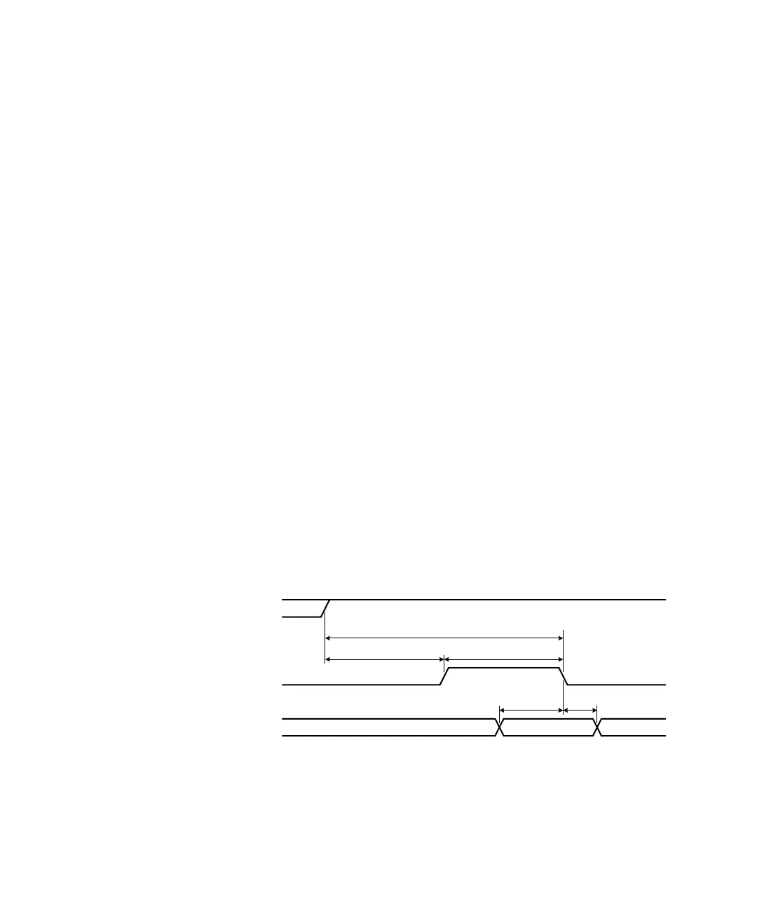
A synchronous unbuffered input is shown in the diagram below
(default handshake line polarity).
H0 (Direction)
H1 (Strobe)
Data In
Don't-Care Valid Don't-Care
T
SETUP
T
HOLD
T
CYC LE
T
CYC LE
/ 2 T
CYC LE
/ 2