Keysight 34950A User’s Guide 21
.
For example, the following SCPI commands set a 34950A in slot 5 to have a 16-bit
output using synchronous handshake. Two data outputs are then performed and
the strobe line is pulsed for each. The I/O direction line is set low following the
first SOURce:DIGital:DATA:WORD command and remains low until the digital
channel is reset of reconfigured.
CONF:DIG:WIDT WORD, (@5101)
CONF:DIG:DIR OUTP, (@5101)
CONF:DIG:HAND SYNC, (@5101)
SOUR:DIG:DATA:WORD #hFFFF, (@5101)
SOUR:DIG:DATA:WORD #h4DB5, (@5101)
Synchronous Buffered Inputs
You can use synchronous mode handshake with buffered (memory) input
operations. (Buffered operations are described in more detail beginning on
page 25.) For buffered input operations, the H0 line acts as a start/stop line. This
line will be set high when the memory input command is executed and will return
low when the memory input operation has completed. The H1 line is not used and
is set to high impedance.
An external strobe input on the H2 line controls the pace of memory transfers. The
sending device must ensure the data is valid before the T
SETUP
and stays valid
until after T
HOLD
. T
SETUP
is 46 ns and T
HOLD
is 10 ns.
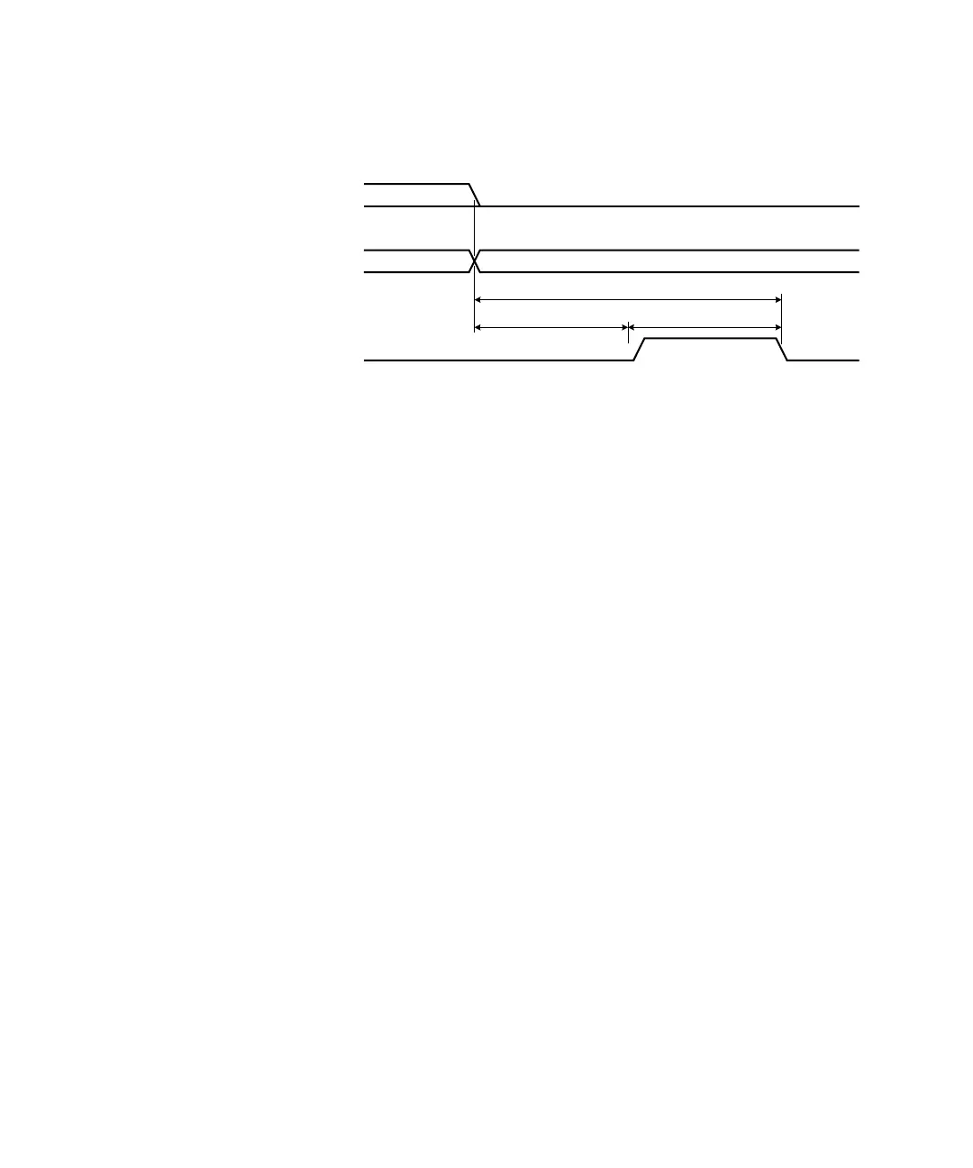
A synchronous buffered input using an external clock is shown in the diagram
below (default handshake line polarity).
H0 (Direction)
H1 (Strobe)
Data Ou t
Invalid Valid
T
CYC LE
T
CYC LE
/ 2 T
CYC LE
/ 2