Keysight 34950A User’s Guide 23
be set such that the device receiving the data can latch the data lines during the
T
CYCLE
time.
The receiving device should detect the leading edge of the strobe line, wait for the
34950A to set the data (T
PD
) and then latch the data. Latching the data on the
trailing edge of the strobe is recommended, however, you can the data following
T
PD
. T
PD
ranges from -23 to 23 ns.
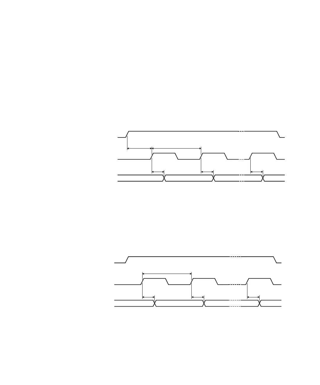
A synchronous buffered output using the internal clock is shown in the diagram
below (default handshake line polarity).
Optionally, you can provide an external strobe input on the H2 line to control the
memory transfers. If you pace the memory inputs from an external clock, the
34950A will sense the leading edge of the strobe and set the data. The data will
be valid after T
PD
and the receiving device may latch the data. T
PD
ranges from 82
ns to 47 ns.
A synchronous buffered output using an external clock is shown in the diagram
below (default handshake line polarity).
H0 (Start/Stop)
H1 (Strobe Out)
Data Ou t
Valid
T
CYCLE
(Last Cycle)
Invalid
T
PD
T
PD
T
PD
T
CYCLE
/ 2
H0 (Start/Stop)
H2 (Clock In)
Data Out
Valid
T
CYCLE
(Last Cycle)
Invalid
T
PD
T
PD
T
PD