8 Service and Maintenance
206 E364xA User’s and Service Guide
Constant Voltage (CV) Verifications
Constant voltage test setup
If more than one meter or if a meter and an oscilloscope are used, connect each to
the (+) and (–) terminals by a separate pair of leads to avoid mutual coupling
effects. Use a coaxial cable or a shielded 2-wire cable to avoid noise pick-up on
the test leads.
Voltage programming and readback accuracy
This test verifies that the voltage programming and GPIB or RS-232 readback
functions are within specifications.
1 Turn off the power supply and connect a digital voltmeter between the (+) and
(–) terminals of the output to be tested as shown in Figure 8-1.
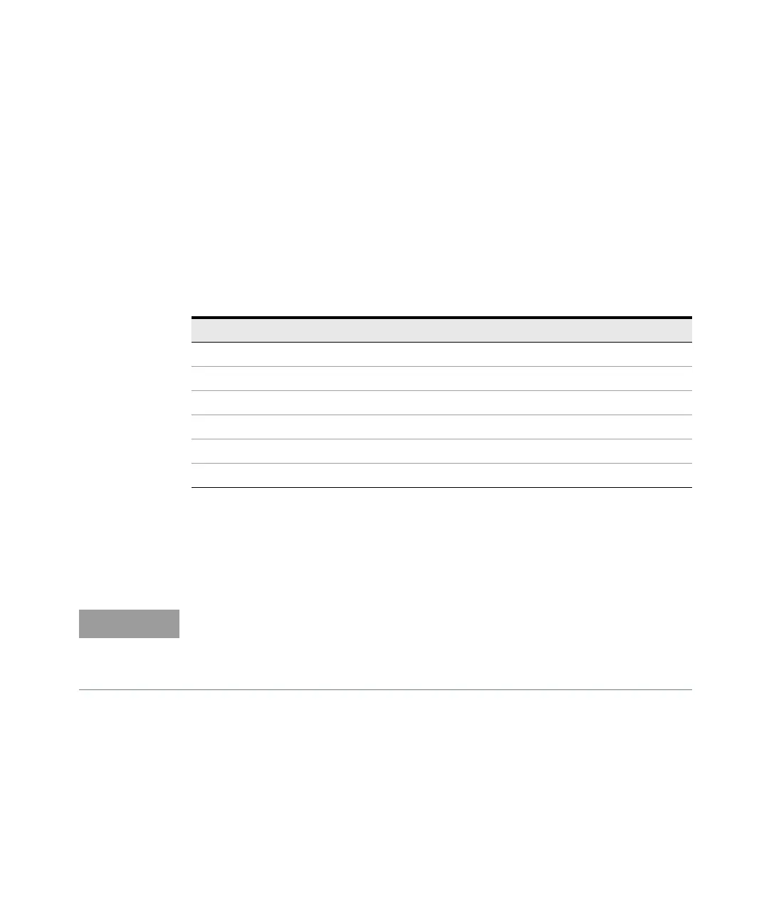
Table 8-5 Verification programming values
Model Low voltage range High voltage range
E3640A 8 V/3 A 20 V/ 1.5 A
E3641A 35 V/ 0.8 A 60 V/ 0.5 A
E3642A 8 V/ 5 A 20 V/ 2.5 A
E3643A 35 V/ 1.4 A 60 V/ 0.8 A
E3644A 8 V/8 A 20 V/ 4 A
E3645A 35 V/ 2.2 A 60 V/ 1.3 A
– The readback values over the remote interface should be identical to those
displayed on the front panel.
– You should program the power supply over the remote interface for this test
to avoid round off errors.
 Loading...


