08 | Keysight | FieldFox Handheld Analyzers - Configuration Guide
FAQs – Applicable To All FieldFox RF and Microwave Analyzers
Question Answer
1. What USB
power sensors
work with
Option 302?
All Keysight U2000x Series USB power sensors are supported with FieldFox.
Visit: www.keysight.com/find/fieldfoxsupport for an up-to-date listing.
2. What is the
difference
between USB
power sensor
(Option 302)
and built-in
power meter
(Option 310)?
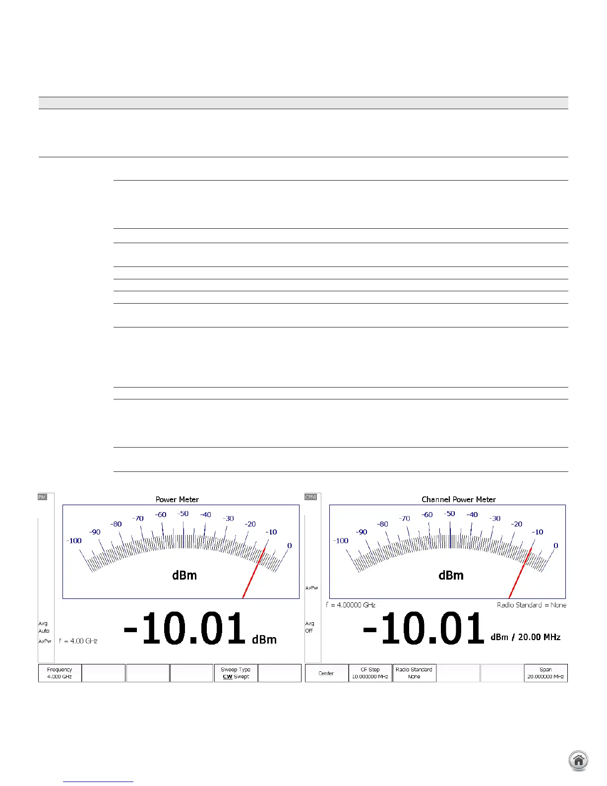
Option 302
USB power sensor
Option 310
Built-in power meter (or channel power meter)
Description Option 302 allows users to connect a
USB power sensor to FieldFox’s USB
port and make broadband power
measurements.
Option 310 is a channelized power measurement capability built
into FieldFox analyzers. Maximum bandwidth is 100 MHz.
External hardware USB power sensor required None. Uses internal receiver.
Power measurement Broadband diode detector, measures
all frequencies
Tuned receiver, so measures frequencies within defined channel
bandwidth
Frequency range Depends on USB sensor Frequency range of the analyzer
Settings Set CW frequency Set CW frequency, Set channel width/span
Power range Depends on USB sensor Depends on channel width and attenuator setting.
Warm-up time 30 minutes to meet accuracy
specifications
No warm-up time required
Accuracy Depends on USB sensor InstAlign accuracy: ± 0.5 dB typical for a CW signal. Since the
measurement is within a certain frequency channel or bandwidth,
to make an accurate measurement, the user needs to know the
exact center frequency and the signal’s bandwidth and set those
accurately.
Programmable Yes, via SCPI Yes, via SCPI
Physical connection The power sensor can easily be
moved to the measurement point,
with a USB cable connecting the
detector to FieldFox.
The measurement point needs to be connected to FieldFox’s RF
input port. If a RF jumper cable is used, the user needs to account
for the loss of the cable with an offset value (can be entered into
the analyzer).
FieldFox source control Yes, on/off, and nominal power level
control
No access to FieldFox’s source from the built-in power meter mode
 Loading...


