Installation Note N9030-90045 19
Option BBA, Analog Baseband I/Q Inputs Retrofit Kit
9. Carefully slide the switch assembly towards the back of the instrument. Assure the cables in the
switch ports are free to slide out.
10.Slightly lift the two semi-rigid cables above the switch assembly and pull the switch away from the
chassis.
Installation of the Flex Ribbon Cable
1. Locate the 8121-2090 flex ribbon cable in the kit. Push the rubber cable protector against the cable
connector on the end of the cable that does not have the ferrite block. When installed, the end of
the cable with the ferrite block will attach to the front panel.
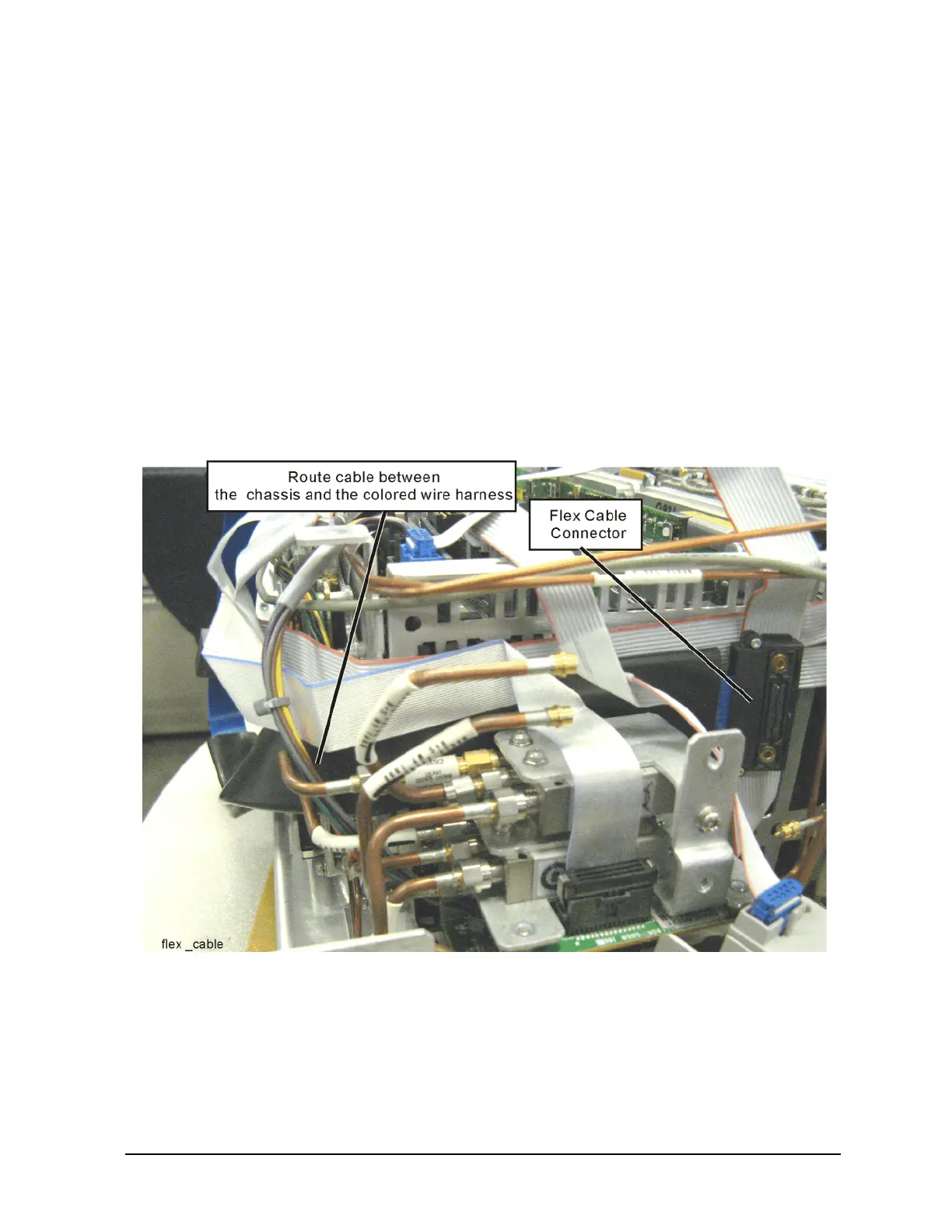
2. Refer to Figure 14. Notice the flex cable orientation. The cable is routed between the chassis and
the colored wire harness. The connection side of the cable is pointing outward. The switch
assembly ribbon cable (if present) and low band assembly ribbon cables are on the outside of the
flex ribbon cable.
Figure 14 Flex Cable
3. Install the flex ribbon cable onto the BBIQ main board. Slide the flex ribbon cable through the slot
in the chassis nearest the BBIQ main board. Make sure the rubber cable protector is against the
cable connector. Assure the pins of the BBIQ main board connector are aligned with the ribbon
cable connector and carefully make the connection.
4. Assure the flex ribbon cable is flat against the chassis and partially behind the switches (if present).
Also ensure there is a very small bit of slack in the flex ribbon cable where it goes through the
chassis so the cable can easily be removed from the BBIQ main board.

 Loading...


