3
WIRING INFORMATION
1. For contactor location please see “Figure 9”. Install the contactor
in a location of your choosing under the hood. There is no
specific location on this machine.
2. UsingtheALTERNATE WINCH WIRING DIAGRAM
(AWWD)(Figure12,pg4)asaguideforsteps2-5,attachthe
BLACKwiretotheBluePostonthewinchandtheREDwireto
theYellowPostonthewinch.
3. RoutethewiresuptothecontactorandconnecttheBLACKwire
totheBluePostonthecontactorandREDwiretotheYellow
PostonthecontactorperAWWD.
4. RoutetheBlueandYellowwiresbacktothebattery.Connectthe
YELLOW POS(+)wiretotheRedpostonthecontactorand
theBLUE NEG(-)wiretotheBlackpostonthecontactorper
AWWD.
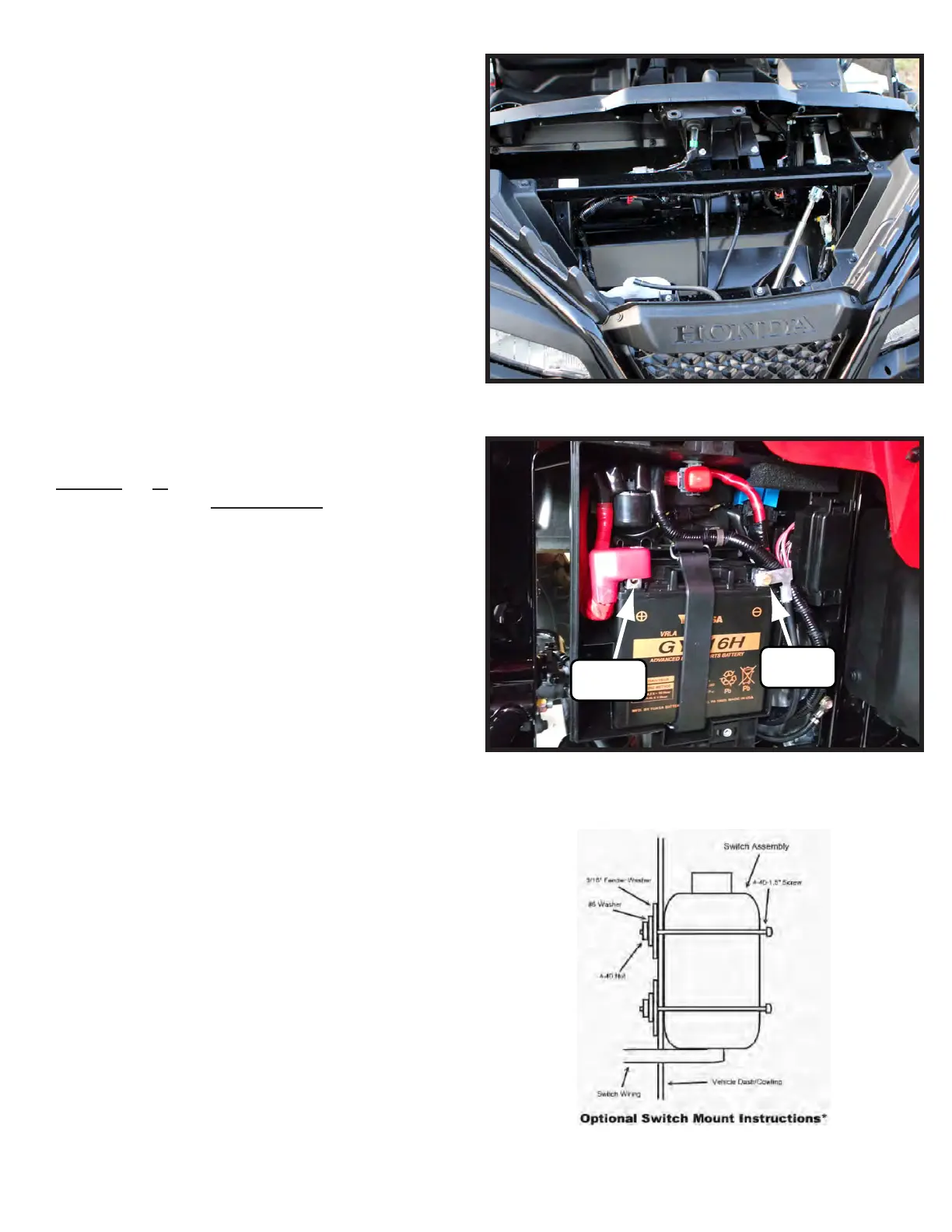
5. AttachtheYELLOW POS(+)wiretothebatteryasshownin
Figures10and12.Then,attachtheBLUE NEG(-)wiretothe
groundpostasshowninFigures10and12perAWWD.
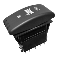
6. Find a location that suits your purposes for the mini-rocker
switch and hand remote.
7. Mini-Rocker Switch Hardware kit. This allows you to mount
your usual handle bar mounted switch to almost any desired
location.
a. Remove handlebar mount hardware from the switch.
b. Locate desired mounting location
c. Mark and drill two switch holes through dash using switch
housing as a template
d. Drill a 3rd hole for the switch wiring.
e. Assemble per Figure 11.
8. Wire the red ignition wire from the controller to a keyed wire.
Typically you can find this on the ignition switch.
“Figure 9” Contactor Location
(+) Positive
Yellow Wire
(-) Negative
Blue Wire
“Figure 10” Battery Location
(Battery is located under the rear passenger fender.)
“Figure 11” Mini Rocker Mounting