EasyManua.ls Logo

KFI 101215 User Manual

KFI 101215
4 pages
To Next Page IconTo Next Page
Page #1 background imageLoading...
Page #1 background image
1
HONDA PIONEER 500
Winch Mount PART # 101215
Hardware Kit: HK-317, HK-031
Kit Components:
Qty. Part Description
1................. Pioneer Winch Plate
2................. Pioneer Bolt Plate
2................. 5/16”-18 x 1-1/4” x 2” U-Bolt
8................. 5/16”-18 x 2.5” Flange Bolt
12............... 5/16”-18 Flanged Nylock Nut
1................. UTV Mini Rocker Hardware Kit (HK-031)
INSTALLATION INSTRUCTIONS:
1.
Placewinchplateoverbumperasshownin
Figure3.Looselysecuretothebumpertubes
usingtheboltplates,2.5”boltsandnuts.Figure 2
shows the different bolting locations.
2.
InstallU-boltsasshowninFigure4andtighten
allhardware.Be sure to tighten U-bolts rst.
“Figure 1”
“Figure 2 Winch Mount Bolting Locations”
“Figure 4 U-bolt Install”
U-BOLT LOCATION
BOLT PLATE
LOCATION
BOLT PLATE
LOCATION
“Figure 3 Mount and Bolt Plate Install”
Question and Answer IconNeed help?

Do you have a question about the KFI 101215 and is the answer not in the manual?

KFI 101215 Specifications

General IconGeneral
BrandKFI
Model101215
CategoryAutomobile Accessories
LanguageEnglish

Summary

Winch Mount Kit Components

Pioneer Winch Plate and Bolt Plate

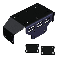
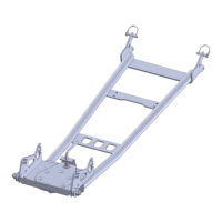
Lists the primary components for the winch mount kit, including the winch plate and bolt plate.

Hardware for Winch Mount

Details the specific hardware required, such as U-bolts, flange bolts, and nylock nuts for mounting.

Winch Mount Installation

Initial Plate Mounting

Describes loosely securing the winch plate to bumper tubes using bolt plates, bolts, and nuts.

U-bolt Installation and Tightening

Instructs on installing U-bolts and tightening all hardware, emphasizing U-bolts first.

Fairlead Plate and Winch Assembly

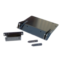
Details installing the roller fairlead to the fairlead plate and then mounting the assembly to the plate.

Final Tightening and Wiring

Covers tightening all bolts and preparing for winch wiring using the provided manual.

Winch Wiring Information

Contactor Location and Connection

Guides on locating the contactor under the hood and connecting winch wires to its posts.

Battery Wiring Connections

Explains connecting winch wires to the battery's positive and negative terminals.

Mini-Rocker Switch Mounting

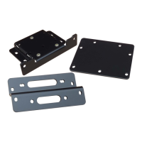
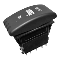
Provides instructions for mounting the mini-rocker switch and hand remote, including drilling.

Ignition Wire Connection

Details wiring the red ignition wire from the controller to a keyed wire, typically on the ignition switch.

Alternate Winch Wiring Diagram

Diagram Overview

Presents a diagram illustrating the alternate wiring method for ATV/UTV applications.

Wiring Connections Summary

Summarizes key connections: winch negative to blue contactor post, positive to yellow, battery negative to black.

Related product manuals