3
KMC50
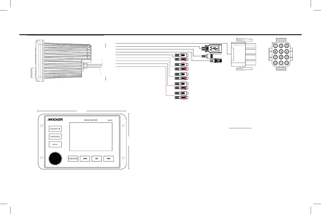
Installation Overview
3” Hole Cutout
Main Harness
1- Red, Switched 12V+
2- White/Blk, Left Front Spkr, Negative
3- White, Left Front Spkr, Positive
4- Orange, Dimmer
5- Grey/Blk, Right Front Spkr, Negative
6- Grey, Right Front Spkr, Positive
7- Blue, Amp Turn-on
8- Green/Blk, Left Rear Spkr, Negative
9- Green, Left Rear Spkr, Positive
10- Black, Ground
11- Purple/Blk, Right Rear Spkr, Negative
12- Purple, Right Rear Spkr, Positive
1
2
3
4
5
6
7
8
9
1. Main Harness
2. USB Port
3. Antenna Input
4. Remote Port
5. AUX Input
6. Front RCA Output
7. Rear RCA Output
8. Sub RCA Output
9. Zone 2 RCA Output
5.5”
3.5”
n