3-1September 2004 90-FM200M-000
FM-200
®
ECS Series Engineered Fire Suppression Systems
CHAPTER 3
FUNCTIONAL DESIGN
3-1 INTRODUCTION
This chapter provides a functional description of the mod-
ules and assemblies in the FM-200
®
ECS Series Engineered
Fire Suppression System.
3-1.1 3" Cylinder Valve
In 2001, Kidde Fire Systems added a 3" discharge valve
to its product line. This valve replaces the 2½" valves
previously used on the 600 lb. cylinder and is a standard
fitting for the 900 lb. cylinder assemblies (also new for
the year 2001). A number of distinct differences between
the 1½", 2" and 2½" valves and the new 3" valve are
detailed in this manual (see Paragraphs 3-3.1, 3-3.7.2,
3-3.7.10, 4-3.11, 4-3.21, 6-2.3 and 6-2.7). Data relating
to the 600 lb. cylinder assembly with a 2½" valve is included
in this manual and is indicated by the reference "old style".
For information on the availability of obsolete products, in-
cluding spare parts, please contact the factory or your Kidde
Representative.
3-2 FUNCTIONAL DESCRIPTION
Compressed FM-200 liquid is held in the agent storage con-
tainer by a discharge valve. When the discharge valve is
actuated, the compressed liquid agent discharges through
the valve outlet and is directed through the distribution pip-
ing to the nozzles. The nozzles provide the proper flow rate
and distribution of FM-200.
The ECS Series Engineered Fire Suppression System is
composed of the following components and assemblies:
Cylinder/valve assembly
Liquid level indicator (optional)
Control head (electric, cable operated, lever operated,
pressure operated and electric and cable operated)
Pressure gauge
Straps and brackets for mounting the cylinder
Cable manual pull station
Nitrogen actuator and mounting bracket
Actuation hose
Flexible discharge hose
Master cylinder adapter kit
Tees, elbows and adapters
Check valve
Valve outlet adapter
Discharge nozzle
Discharge indicator
Corner pulley
Supervisory pressure switch (optional)
Hydrostatic test adapter
FM-200 cylinder recharge adapter
FM-200 cylinder seating adapter
Main to reserve transfer switch
Manifold El-check
Detector
Pressure operated switch and trip
Control panel
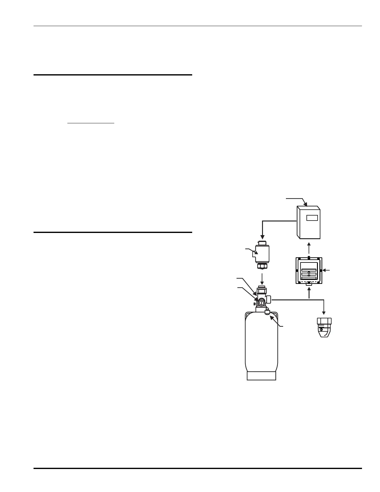
Figures 3-1 and 3-2 show the above components in two
typical configurations.
FM-200
Cylinder
PRESSURE OPERATED SWITCH
3P.D.T.
U
L
FM
Fire Suppression
Panel
Electric
Control
Head
Liquid
Level
Indicator
Pressure
Gauge
Valve
Nozzle
Pressure
Operated
Switch
Figure 3-1. Typical FM-200 System with
Electric Control Head
 Loading...