3-7September 2004 90-FM200M-000
FM-200
®
ECS Series Engineered Fire Suppression Systems
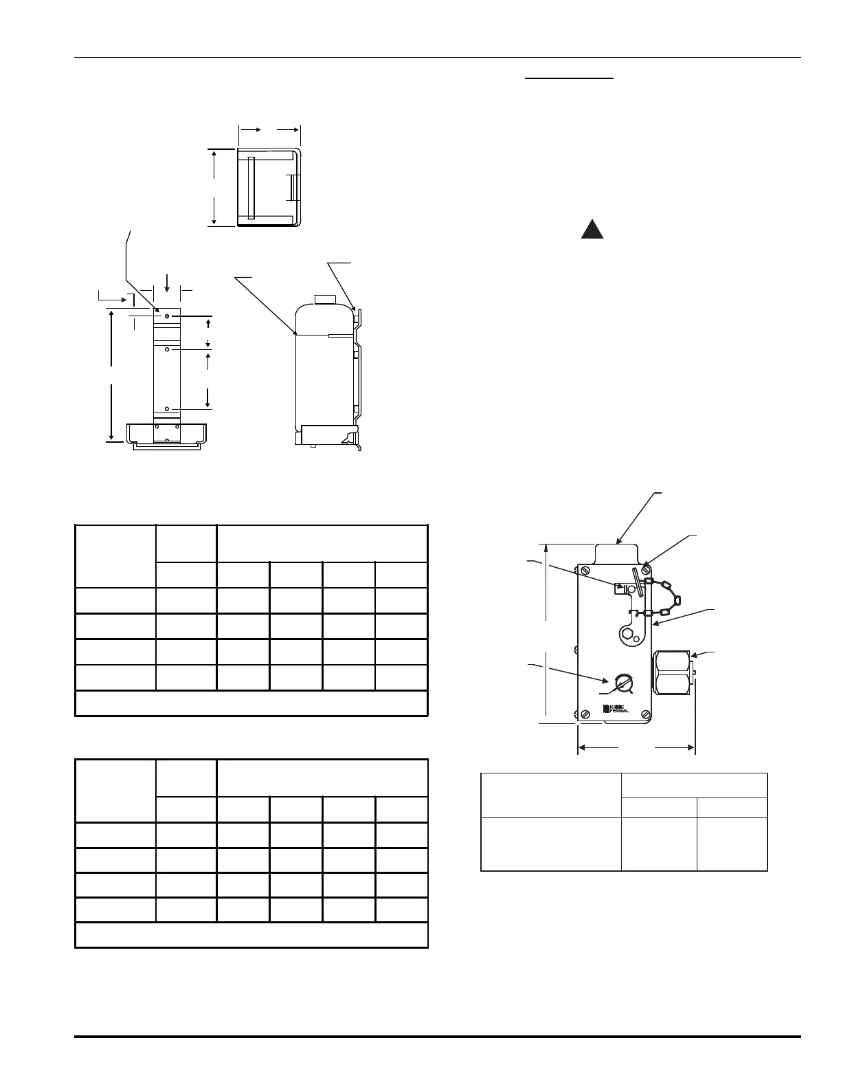
Wall brackets (P/N 486485, 486486, 486487 and 486488)
are available for the 10, 20, 40 and 70 lb. size cylinders
(see Figure 3-10 and Tables 3-8 and 3-9).
B
A
3.00”(76.2 mm)
3.00”
(76.2 mm)
.62”
(15.75mm)
.406” DIA. THRU
(3) MTG HOLES
(TYP)
FLEXIBLE
STRAP
3/8” FASTENING
HARDWARE (TO
WALL)
D
C
Figure 3-10. Cylinder Wall Brackets
Table 3-8. DimensionsCylinder Wall Brackets
Part Number
Cylinder
Capacity
Dimensions*
lb.ABCD
486485 10 8.62 1.56 7.68 5.75
486486 20 14.37 7.31 7.68 5.75
486487 40 13.12 5.94 9.75 6.75
486488 70 19.62 12.44 9.75 6.75
*Note: Dimensions are in inches.
Table 3-9. DimensionsCylinder Wall Brackets, Metric
Part Number
Cylinder
Capacity
Dimensions*
lb. A B C D
486485 10 218.95 39.62 194.31 146.05
486486 20 264.99 185.67 195.07 146.05
486487 40 333.25 150.88 247.65 146.05
486488 70 498.35 315.98 247.65 146.02
*Note: Dimensions are in millimeters.
3-3.4 Control Heads
A suitable control unit, specifically Listed and Approved for
use with the following electric control heads, shall be pro-
vided for supervision of the releasing circuits per NFPA re-
quirements. In addition, a 24-hour back-up power source
shall be provided per NFPA requirements.
3-3.4.1 ELECTRIC CONTROL HEADS,
P/N 890181, P/N 890149 AND P/N 890165
CAUTION
!
The stackable control head (P/N 486500-01)
cannot be used with 3" valve cylinders
(P/Ns 90-100600-100, 90-100601-100, 90-100900-
001 and 90-100901-001). The stackable control
head does not have sufficient force to activate
the 3" valve (P/N 90-17000-000) and may result
in a system failure. The electric/manual control
heads (P/Ns 890181, 890149 and 890165) may
be used with the 3" valve.
The Electric Control Head provides for electric actuation of
the FM-200 cylinder valve. It is operated electrically from a
detection and control system, a remote manual station, or
locally with a manual lever on the electric control head
(P/N 890181 only). See Figure 3-11.
PU
ELECTRIC
CONTROL HEAD
VOLTS
AMPS
PART NO.
SET RELEASED
MADE IN U. S. A.
TO RESET
USE SCREWDRIVER
CONNECTION FOR FLEXIBLE
ELECTRIC CONDUIT -
3/4” NPT FEMALE
LOCKING PIN
LOCAL MANUAL
RELEASE LEVER
SWIVEL NUT
Control Head
Part Number
890181
890149
890165
(a)
(a),(b)
Voltage
24 Vdc
Current
2.0A
KIDDE-FENWAL, INC.
400 MAIN STREET
ASHLAND, MA 01721
INDICATOR AND
RESET STEM
6.18"
4.00"
(102 mm)
(157 mm)
SEAL WIRE
(a) Not FM Approved for use with FM-200 Systems
(b) Not UL Listed for use with FM-200 Systems
115 Vac
125 Vdc
1.0A
0.3A
Figure 3-11. Electric Control Head
 Loading...