Do you have a question about the Kidde SA-ETH and is the answer not in the manual?
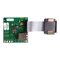
The SA-ETH Ethernet Interface Card is designed to provide a standard 10/100 Base-T Ethernet network connection, enabling communication with a local network. This card serves as a crucial component for various functions, including uploading and downloading panel configurations, accessing historical data, and checking current status. It facilitates communication with a PC running a configuration utility or connects to a compatible central monitoring station receiver over a network, enhancing the system's connectivity and remote management capabilities.
The primary function of the SA-ETH card is to establish a reliable Ethernet connection for a fire alarm or security panel. This connection allows for the seamless transfer of data between the panel and external systems. For instance, system administrators can use the card to remotely configure panel settings, retrieve event logs, and monitor the real-time status of the system from a connected PC. This capability significantly reduces the need for on-site visits for routine maintenance and configuration tasks, improving operational efficiency.
Furthermore, the SA-ETH card supports communication with central monitoring stations. By connecting to a compatible receiver, the panel can transmit alarm signals, trouble conditions, and other critical events to a monitoring center. This ensures that emergency services or designated personnel are promptly notified of any issues, enhancing the overall safety and security of the monitored premises. The card's ability to integrate with network-based monitoring solutions makes it a versatile component in modern fire and security systems.
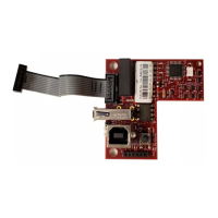
The card is designed to be installed within the plastic assembly of the main panel and connects to the main circuit board via a ribbon cable. This modular design allows for easy integration and replacement, simplifying installation and maintenance procedures. Once installed, the card must be configured through programming to ensure proper operation within the network environment. This configuration process typically involves setting network parameters such as IP addresses and connection modes, which are essential for establishing stable communication.
The SA-ETH card offers several usage features that enhance its functionality and ease of integration. It supports both RJ-45 patch cables and RJ-45 crossover cables, providing flexibility in network cabling options. This adaptability allows installers to choose the most suitable cable type based on the existing network infrastructure and specific connection requirements. Whether connecting directly to a PC or integrating into a larger network via a router or switch, the card accommodates various setups.
The card includes four LEDs (Light Emitting Diodes) that provide visual indications of its status and network activity. These LEDs are crucial for troubleshooting and monitoring the card's operation.
These visual indicators allow installers and technicians to quickly assess the card's operational status and diagnose potential network problems without requiring specialized diagnostic tools. For example, if the "Link" LED is off, it suggests a problem with the physical cable connection or the network device it's connected to. If the "Collision" LED is frequently active, it might indicate network congestion or misconfiguration.
Maintenance of the SA-ETH card is straightforward, primarily due to its modular design and diagnostic LEDs. The installation process itself is designed to be simple, involving sliding the card into a designated slot on the plastic assembly and securing it with screws. Connecting the ribbon cable to the main circuit board and then attaching the network cable completes the physical installation. This ease of installation also translates to ease of replacement, should the card ever need servicing.
Before any installation or maintenance, it is crucial to power down the panel by first disconnecting the batteries and then the main AC power. This safety measure prevents electrical hazards and potential damage to the components. Once the card is physically installed, it requires configuration through programming. This typically involves accessing the panel's programming interface to set network parameters, ensuring the card operates correctly within the network environment. Regular checks of the LED indicators can help in proactive maintenance, allowing technicians to identify and address potential network issues before they escalate.
The card's robust design and clear installation instructions contribute to its low maintenance requirements. By following the provided steps for installation and configuration, users can ensure reliable operation. In the event of a network issue, the LED indicators serve as a first line of diagnosis, guiding technicians to the source of the problem, whether it's a cable issue, a network device problem, or a configuration error. This self-diagnostic capability minimizes downtime and simplifies troubleshooting efforts, making the SA-ETH card a practical and manageable component in any integrated system.
| operating voltage | 24 VDC |
|---|---|
| operating current (standby/alarm) | 34 mA |
| max operating current | 41 mA |
| temperature range | 32 to 120°F (0 to 49°C) |
|---|---|
| relative humidity | 0 to 93% noncondensing at 90°F (32°C) |
| max wire runs | 200 feet (60 m) |