Chapter 5: Installation
P/N 3101890-EN • REV 006 • ISS 21JUN18 99
Figure 32: Uninterruptible power supply wiring
(1) 120 VAC, 15 A circuit
(2) UPS trouble contact monitor
Connecting a CDR-3 for coded tone output
The CDR-3 Bell Coder module can be connected to the AUX input on the VM-PMI EAEC card to provide a coded
or march time tone to the audio system. See Table 33 below for power and installation specifications.
Table 33: CDR-3 power and installation specifications
power
Input voltage
Standby current
24 VDC nominal
60 mA
Standby
Alarm
60 mA
100 mA
Half-footprint space on the back of the CAB6 backbox (see Figure 21 on page 79 for
the footprint location)
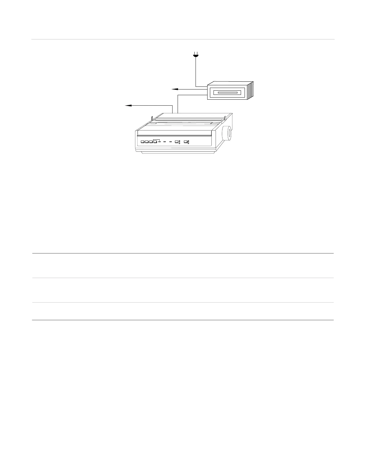
When connecting a CDR-3 to a serial port that is shared with an MIR-PRT/S printer, you must connect both
devices using an IOP3A.
IOP3A isolator module
The IOP3A isolator module provides two RS-232 connections that allow you to connect a CDR-3 for coded tone
output when a MIR-PRT/S printer is connected to the control panel. See Table 34 for power and installation
specifications.
(1)
LINE
FEED
FORM
FEED
TOP
SET
SELECT ALARM POWER PITCH MODE
SYSTEM PRINTER
PT1-P
MIR-PRT/1S
VM-CPU
UPS
(2)