Chapter 6: Preventive maintenance and testing
110 P/N 3101890-EN • REV 006 • ISS 21JUN18
CO maintenance alert
In addition to displaying a maintenance alert when the photo element dirtiness is at or above 80%, the loop
controller also displays a maintenance alert when the CO sensor module is at or below 6 months until end-of-life.
If both elements reach or pass these thresholds, there is only one maintenance alert.
Once the dirtiness threshold is at 100%, a dirty detector trouble displays for the photo element. Once there are
zero months until end-of-life, the panel displays the CO end-of-life trouble message.
CO maintenance trouble
The CO sensor module has a life span of 6 years. After 6 years, the detector sends out an end-of-life trouble
message. When the message is transmitted, replace the CO sensor module.
To determine the months until end-of-life, run a maintenance report from the LCD screen. See “Device
maintenance reports” on page 41.
Modules
Visually inspect the modules to ensure the physical installation is secure. Perform functional testing of the module
regularly as required by the AHJ.
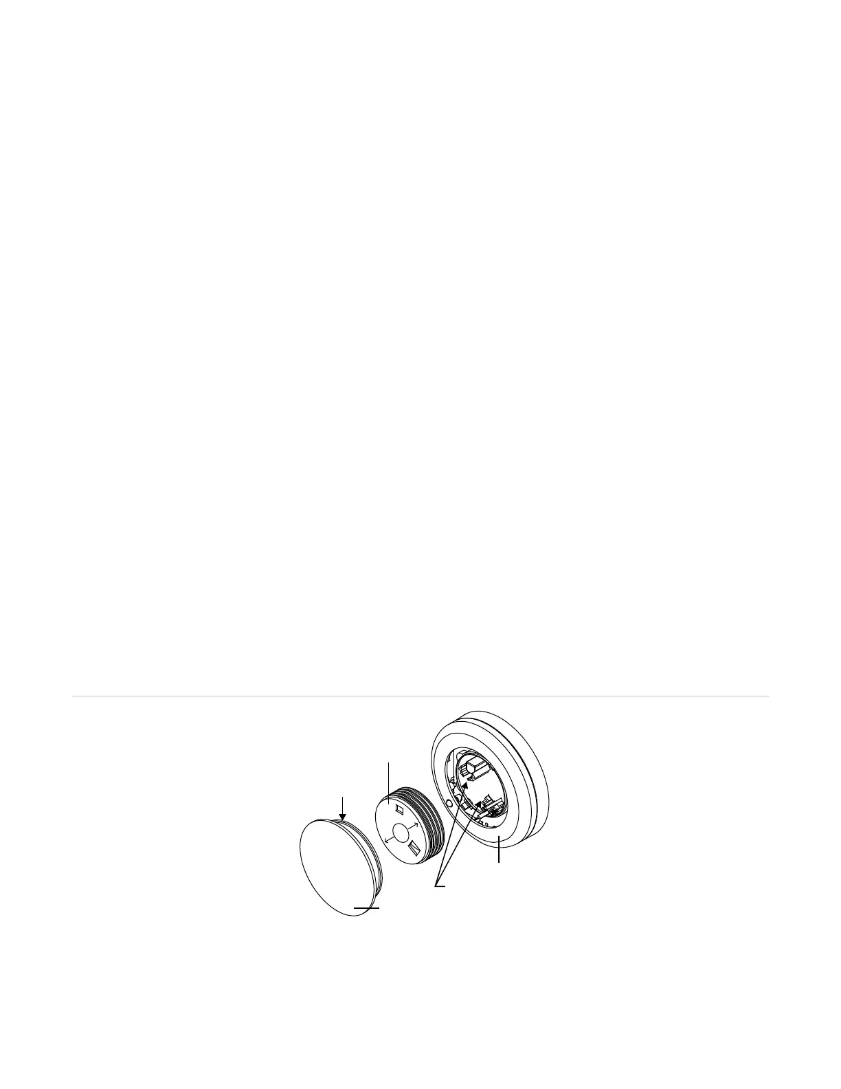
Replacing a V-Series detector optical chamber
1. Remove the detector from the base.
2. Insert a screwdriver in the small slot on the detector cap. See Figure 37 below.
3. Pry the cap off the detector body.
4. Squeeze the two arrows labeled “squeeze here,” on the optical block chamber, and the pull off the chamber.
5. Blow off the optical block base using clean compressed air.
6. Snap a new optical block chamber in place. Make sure you line up the two arrows on the block chamber with
t
he snaps on the optical block base.
7. Connect the detector cap to the detector body by rotating the cap clockwise until it snaps into position.
8. Install the detector onto the base.
9. Test the detector and verify sensitivity.
Figure 37: V-Series detector optical chamber
2) Optical block chamber
(5) Detector cap
Detector body
S
q
u
e
e
z
e
H
e
r
e
Detector cap
Optical block
chamber
Slot to insert
screwdriver
Optical block base
(1)
(2)
(3)
(4)
(5)