Chapter 2: Product description
P/N 3101890-EN • REV 006 • ISS 21JUN18 7
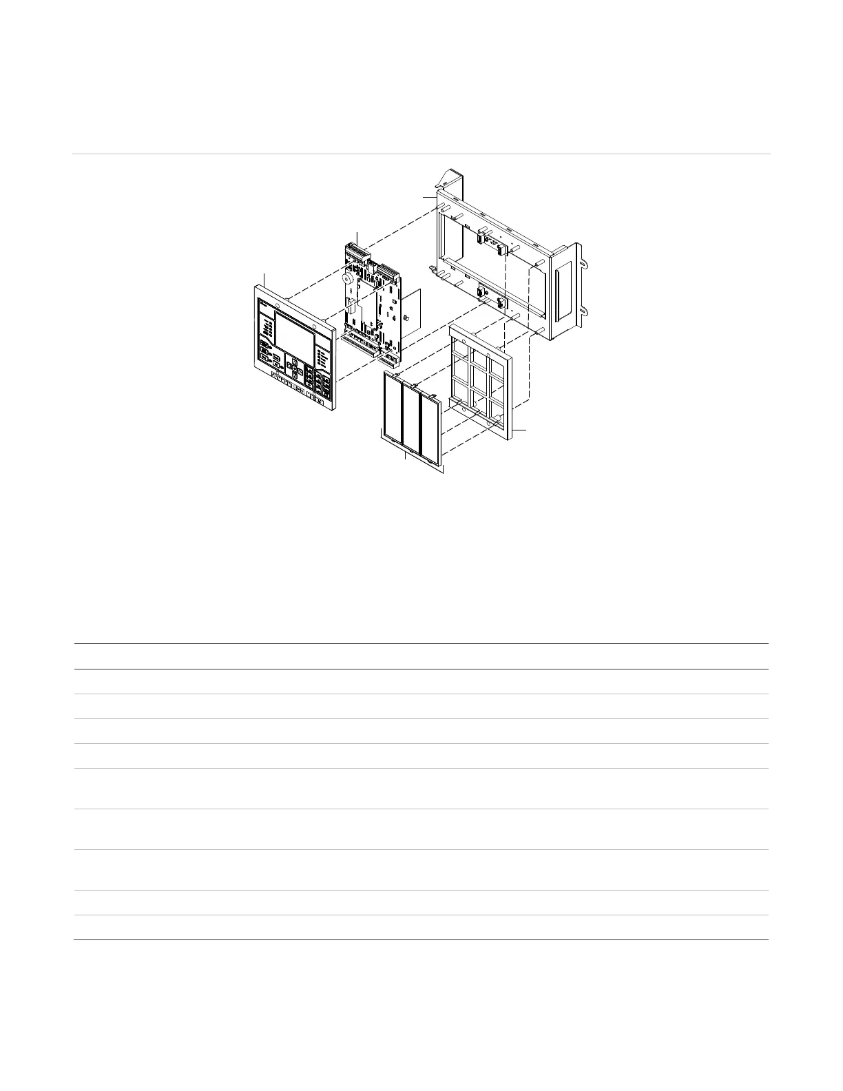
Electronics chassis assembly
Figure 3 provides an exploded view of the VM-ELEC.
Figure 3: VM-ELEC electronic chassis assembly, exploded view
(1) Electronics chassis
(
2) VM-CPU Main Board
(3) VM-LCD User Interface
(5) Filler plates
System size
Table 1 lists the maximum hardware capabilities for a single VM-1 control panel.
Table 1: Control panel hardware capabilities
Maximum capacity
Signaling line circuits (
SLC) 4 [1]
500 (125 detectors each SLC)
500 (125 single address modules each SLC)
Notification appliance circuits
4 Class B or Class A [2]
4 continuous, programmable
1 continuous or resettable
30 (30 sets of system controls and 3,840 LED
indicators)
30 (30 sets of system controls, 1,920 switches, and
3,840 LED indicators)
3
etworked fire alarm control panels 24
[1] One built-in dual loop controller on the CPU plus one dual loop controller module installed on the chassis rail.
[2] A CLA-PS10 Class A Adapter Card must be installed to convert the Class B notification appliance circuits to
Class A notification appliance circuits.