Appendix A: System calculations
182 P/N 3101890-EN • REV 006 • ISS 21JUN18
25 or 70 VRMS NAC wire length
The maximum allowable wire length is the farthest distance that a pair of wires can extend from the amplifier to
the last speaker on the notification appliance circuit without losing more than 0.5 dB of signal. Calculating the
maximum allowable wire length using this method ensures that each speaker operates at its full potential.
Several factors influence the maximum allowable wire length:
• Wire size
• Output signal level of the amplifier driving the circuit
• Number of speakers installed on the circuit
To calculate the maximum allowable wire length for a 0.5 dB loss, use the following formula:
Maximum length = (59.25 × Amplifier output²) / (Wire resistance × circuit load)
Where,
• Amplifier output is the signal level in VRMS supplied by the amplifier driving the circuit
• Circuit load is the total watts required by the audio circuit
• Wire resistance is the resistance rating of the wire per 1000 ft pair. See Table 73.
For example, the maximum allowable wire length for an audio circuit consisting of a 30 W, 25 VRMS amplifier
driving thirty 1 watt speakers, using 18-gauge wire would be 95 ft
94.95 = (59.25 × 25²) / (13 × 30)
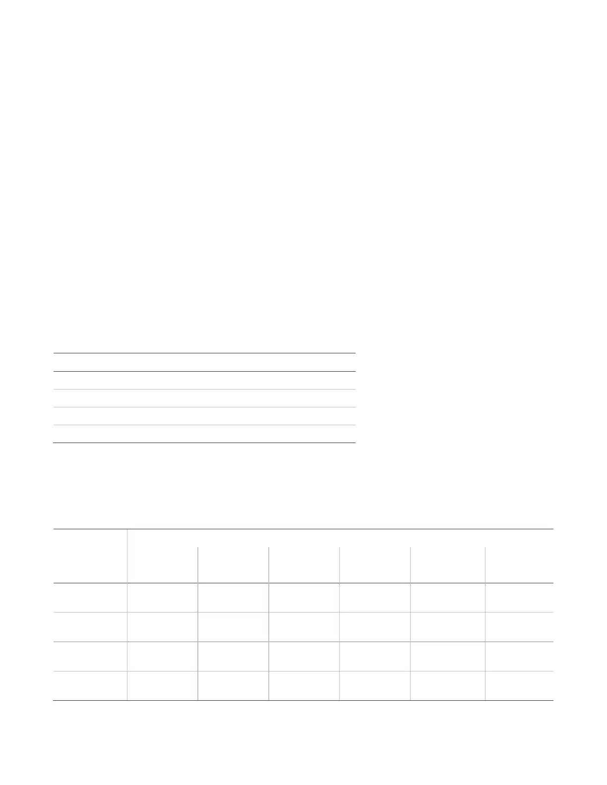
Table 73: Wire resistance ratings
Resistance per 1,000 ft pair (ohms)
13.0
8.0
5.2
) 3.2
Table 74 and Table 75 give the maximum allowable wire lengths for various wire sizes and loads. Use Table 74
when designing circuits for amplifiers set for 25 VRMS output. Use Table 75 when designing circuits for amplifiers
set for a 70 VRMS output.
Table 74: Maximum allowable length at 25 VRMS, 0.5 dB loss
Circuit load requirement
15 W 20 W 30 W 40 W 95 W 120 W
ft m ft m ft m ft m ft m ft m
190 58 142 43 95 29 71 22 Over max
current limit
Over max
current limit
309 94 231 70 154 47 116 35 48.7 15 39 12
475 145 356 109 237 72 178 54 75 23 59 18
772 235 579 176 386 118 289 88 121.8 37 96 29