Chapter 2: Product description
P/N 3101890-EN • REV 006 • ISS 21JUN18 13
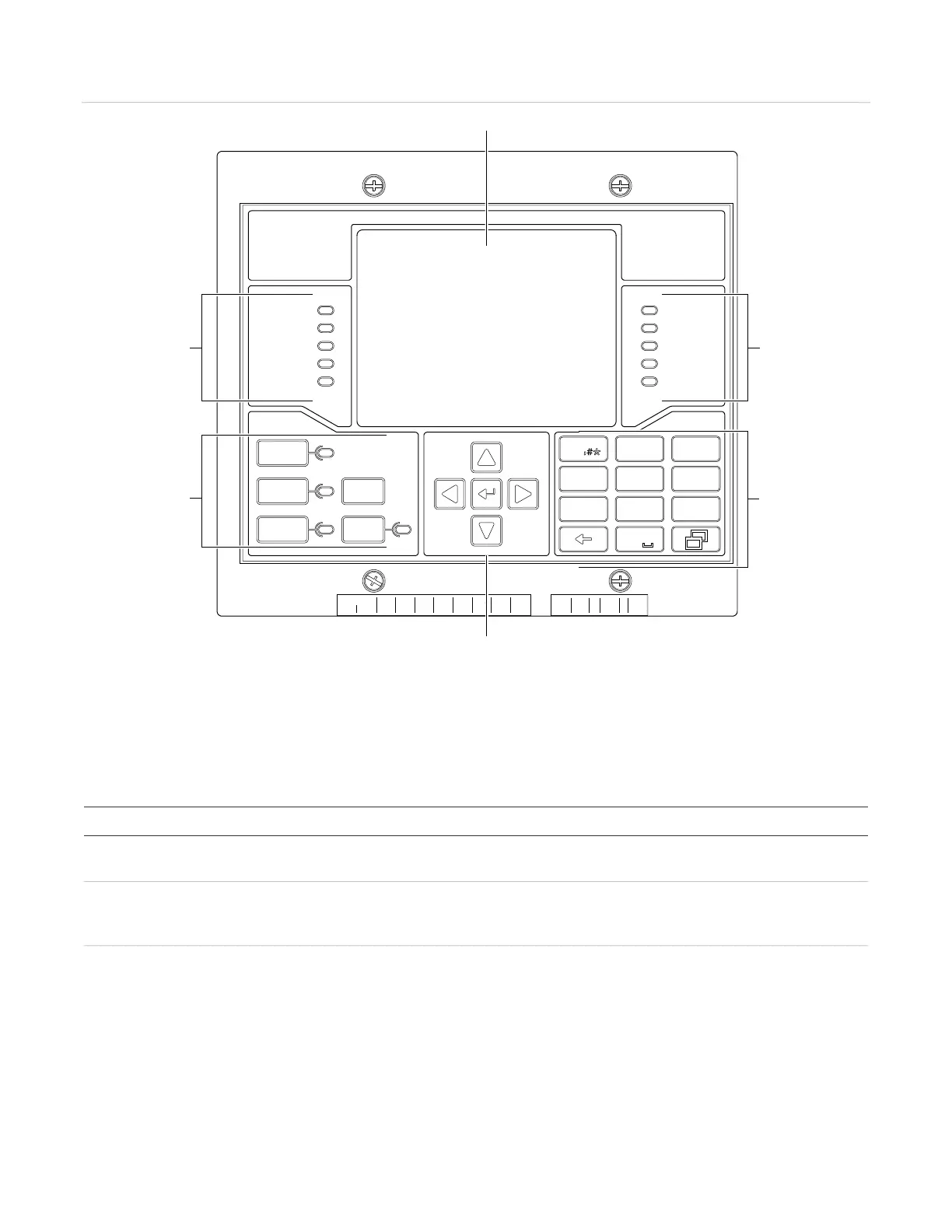
Figure 4: VM-1 user interface
2) System status indicators
(3) Common controls and indicators
(5) Alphanumeric keypad
Operator controls and indicators
Table 5: User interface operator controls
Description
screen Backlit liquid crystal display, 240 × 320 pixels, 24 lines of 40 characters. The LCD
provides information relevant to the current condition of the control panel.
control and LED
Pressing the button acknowledges an active event. The control panel buzzer only
silences after all events have been acknowledged. The LED indicates the panel is in
an off-normal condition and that the panel has been placed in Panel Silence mode.
common
LED
Pressing the button turns off the emergency voice/alarm communications (EVAC)
Alert channels, and all active audible and visible notification appliance circuits.
Pressing the button a second time turns the notification appliance circuits back on.
The LED indicates that the active notification appliance circuits have been silence.
The Alarm Silence function can be configured to require an access level password.
ACK/Panel
Silence
Alarm
Silence
Reset
Drill
Details
Power
Tes t
Ground
Fault
Monitor
Service
Detector
Supervisory
Alarm
Trouble
Disable
CPU Fail
1
4
7
2
5
8
3
6
9
0
ABC
JKL
TUV
DEF
MNO
WXYZ
GHI
PQRS
VM
SERIES
B
+-
LOOP2
2
B
H
S
A
+
-
LOOP2
A
B
+-
LOOP2
B
24+
AUX
C
M
K
S
W
R
P
NETWORK AUDIO
AUDIO AUDIO AUDIO
OUT
IN
+ -
B B
A IN
A OUT
B IN
B OUT
+ -
+ - +
- + -
A B
RS-485
+- +
-
RS-485
R
X
1
A A
+ -
T
X
1
T
S
1
R
O
M
1
C
BUS
BUS
(1)
(2) (2)
(5)
(3)
(4)