Chapter 5: Installation
82 P/N 3101890-EN • REV 006 • ISS 21JUN18
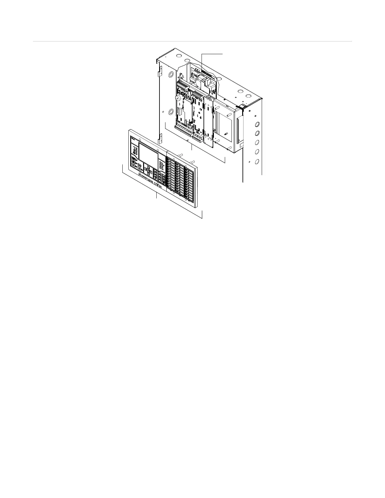
Figure 23: VM-ELEC chassis hardware and operator layer devices
(1) PS10-4B. A protective cage is installed over the power supply for ULC applications
(2) Hardware layer components (VM-CPU and VM-DACT or VM-SLCXB)
(3) Operator layer components (VM-LCD and D12LS-VM modules)
VM-CPU Main Board
The VM-CPU Main Board is a hardware layer board that processes all information from modules installed in the
same cabinet and from other control panels on the life safety network. One main board is required for each panel
in a VM-1 network. The VM-CPU is always installed on the first three card spaces.
One VM-SLC signaling line circuit card for signaling line circuit 1 (SLC1) is preinstalled on the VM-CPU. The
signaling line circuit supports up to 125 detector and 125 module addresses. It also provides dedicated non-
resettable 24 VDC for powering conventional two-wire smoke detector circuits on GSA modules. See the
VM-CPU Main Board Installation Sheet (P/N 3101798-EN) for connecting field wiring and for specifications.
Option cards
The VM-1 control panel has one card address for an optional VM-DACT card or VM-SLCXB card. It is installed
next to the VM-CPU on the electronics chassis. See the “Panel components” section on page 8 for a list of panel
options and accessories.
Notes
• If control-indicating modules are not installed, consider installing the filler plates that came with the VM-ELEC
chassis to cover the spaces.
• If the project requires a VM-DACT option card, see “VM-DACT Dual Line Dialer Card” on page 90 for
configuration instructions as well as the installation sheet received with the module.
• If the project requires a VM-SLCXB option card, see the VM-SLCXB Signaling Line Loop Controller
Expansion Card Installation Sheet (P/N 3102128-EN) for installation instructions and specifications.