4-12 Remote Control PAS SERIES
• If Vext comes loose, erroneous operation may result
due to external noise. Securely connect the wires to
the J1 connector.
• Do not apply voltage or reverse voltage exceeding
1
0.
5 V across the external voltage control pins. Oth-
erwise, damage to the unit may result.
• The input impedance across the external voltage control pins
is approximately 30 kΩ.
• Use a low-noise and stable voltage source for Vext. The noise
in Vext is multiplied by the amplification factor of the unit
and appears at the unit's output. Thus, the output ripple noise
may not meet the unit's specifications.
•
To minimize the influence of noise on the output, use a 2-core
shielded wire or a twisted-pair wire to connect the control ter-
minals and Vext. Make the wires as short as possible.
Susceptibility to the effects of noise increases as the wires get
longer. When wires are long, proper operation may be hin-
dered even if a cable with anti-noise measures is used.
When using a shielded cable, connect the shield to the - (neg.)
output terminal. If the shield needs to be connected to the Vext
side, see next page " Connecting the Shield to the Vext Side".
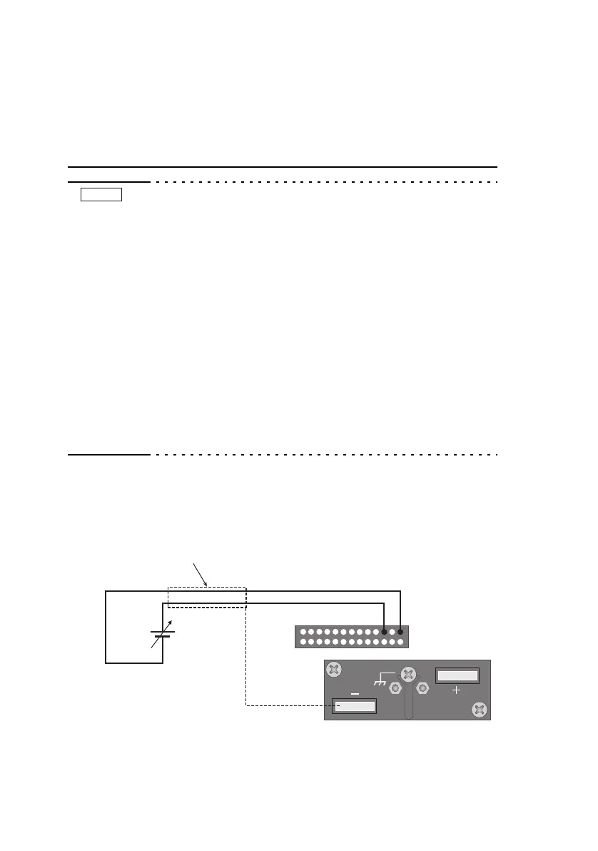
■ External voltage source (Vext) connection
Pins 1 and 5 of the J1 connector are used.
Fig.4-4 Connection of the output current control using
e
xte
rnal voltage
NOTE
J1
1525
2
13
1426
2-core shielded or
twisted-pair wire
Vext
+
–
 Loading...