Do you have a question about the Kiln Sitter P and is the answer not in the manual?
Explains the value and engineered performance of the KILN-SITTER® control for years of trouble-free operation.
Warns that the KILN-SITTER® is not a fail-safe device and the kiln should not be left unattended.
Instructs users not to fire the kiln over or near flammable materials like wood floor or carpeting.
Details the one-year warranty for defects and lists specific exclusions like damage from overfiring or misuse.
Introduces the KILN-SITTER® as a control that allows users to enjoy their hobby more by monitoring the kiln.
Explains the mechanical control fires the kiln using time and temperature, with a cone or bar determining shut-off.
Notes that the KILN-SITTER® requires little attention but may need occasional adjustment or part replacement.
Recommends following instructions and test firing an empty kiln before any other operations for proper adjustment.
First step in adjustment procedure: ensure all kiln switches are turned off.
Instructs to install the firing gauge over the sensing rod and cone supports.
A critical reminder to remove the firing gauge before operating the kiln.
Guides checking the clearance between the release claw and the weight trigger.
Details the specific 1/16-inch clearance needed between the claw tip and trigger face.
Reiterates the warning against placing the kiln near flammable materials to prevent fire hazards.
Confirms that the firing gauge has been removed as a prerequisite for test firing.
Instructions for applying kiln wash thinly to cone supports and sensing rod for test firing.
Step to raise the weight up against the guide plate before inserting the cone.
Instruction to press the claw down lightly until it engages the trigger mechanism.
Guides on carefully placing the test cone onto the cone supports.
Emphasizes correct cone positioning is crucial for proper firing and preventing kiln damage.
Check the sensing rod for free and centered travel before each firing.
Ensure all kiln switches are turned off before engaging the KILN-SITTER®.
Apply a thin coat of kiln wash to cone supports and sensing rod, allowing it to dry.
Advise on positioning ware to keep the KILN-SITTER® tube, supports, and cone visible.
Step to raise the weight up against the guide plate as part of the firing preparation.
Instructs to press the claw down lightly until it engages the trigger.
A critical warning against using any lubricants on the KILN-SITTER® components.
Recommends repeating adjustment checks every 30 firings to maintain proper function.
Explains leaving the top peephole open to reduce deterioration and increase tube assembly life.
Advises on cleaning cone supports and rotating or replacing them if wash or glaze cannot be removed.
Highlights the swivel/pivot as sensitive, recommending inspection every 6-12 months due to corrosion risk.
Notes that high-fire temperatures can deteriorate the sensing rod, affecting trigger and claw adjustment.
States the KILN-SITTER® is designed for temperatures up to Cone 8, with higher temps reducing component life.
A critical safety instruction to ensure the power is off before starting tube replacement.
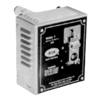
Directs users to Page 2 for an exploded illustration and part names for Model P.
Step-by-step instruction to remove the box from the baffle plate by unscrewing machine screws.
Instruction to remove the baffle plate using 3/8-inch metal screws for withdrawal from the kiln.
Details on disassembling the old tube by removing the large nut and washer from the baffle plate.
Guides on inserting the new tube and nipple through the baffle plate, ensuring proper spline engagement.
Instructs to align the sensing rod end with or behind the cone supports, adjusting the setscrew if needed.
A critical safety instruction to ensure the power is off before starting tube replacement.
Directs users to Page 2 for an exploded illustration and part names for Model K.
Explains removing the guide plate screws to access the tube's attachment screws on the front plate.
Instruction to remove the flat-headed screws that secure the tube to the front plate.
Details on freeing the front plate from the kiln wiring box by removing its screws.
Guidance on pulling the plate forward to allow room for old tube removal and new tube installation.
Instructs to attach the new tube, referring to diagrams for correct positioning.
Step to replace the front plate back onto the kiln wiring box after tube installation.
Notes that counterweights are not required for short and long tube assemblies.
Final step to adjust and test fire the newly installed tube as per the manual's front section.
Indicates that heating rates shown are examples, maintained during the last degrees of temperature rise.
Details that the specified heating rates were maintained during the final degrees of temperature rise.
Explains that temperature equivalents may not be exact for all firing conditions, recommending further data.
| Brand | Kiln Sitter |
|---|---|
| Model | P |
| Category | Control Unit |
| Language | English |