© 2021 Carrier. All rights reserved. 1 / 16 P/N 10-5151-501-108-02 • ISS 09JUN21
KAL714C Addressable Conventional 4-Zone
Module Installation Sheet
EN ES IT PT FR NL CS NO PL HU
EN: Installation instructions
Description
The KAL714C is used to connect four conventional zones to an
addressable fire system.
The module may be used in detection systems with no area
subdivision and/or when exact location data is not required.
One module allows for connection of up to 20 conventional
detectors per zone and an unlimited number of manual call
points or normally open (NO) contacts to the fire detection
system.
Installation
Caution: For general guidelines on system planning, design,
installation, commissioning, use and maintenance, refer to the
EN 54:14 standard and local regulations.
Module Installation
Disconnect the fire system power supply and install the module
in the protective housing provided.
Connect the loop cable shield wire to the earth screw and
install a 4.7 kΩ end-of-line resistor at the end of the detection
zone.
The 24 V power supply for the module must be provided by an
auxiliary power source.
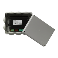
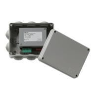
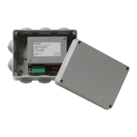
Connection
The module connectors, DIP switch, and status LED are
shown in Figure 1:
1. Earth screw
2. Status LED
3. Loop connectors
4. Auxiliary power supply connectors
5. DIP switch
6. Zone connectors 1 to 4 (left to right)