2 / 12 P/N 10-4221-501-KL7C-02 • ISS 06FEB20
Specifications
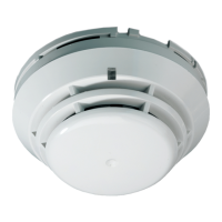
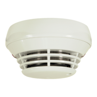
KL710 KL731/KL731B
18 to 28 VDC 9 to 28 VDC
Standby
Alarm
70 µA
100 mA
85 µA
100 mA
alarm indication Flashing LED Flashing LED
Constant LED Constant LED
60 to 80 m
2
60 to 80 m
2
IP42 IP42
KZ700, KZ700B
KZ705, KZ705D,
KZ700, KZ700B
KZ705, KZ705D,
KZ705R
Operation
Storage
−10 to +60ºC
−10 to +70ºC
−10 to +60ºC
−10 to +70ºC
10 to 95%
noncondensing
10 to 95%
noncondensing
White White/Black
) 99 × 45 mm 99 × 45 mm
71 g 106 g
Regulatory information
This section provides a summary on the declared performance
according to the Construction Products Regulation
(EU) 305/2011 and Delegated Regulations (EU) 157/2014 and
(EU) 574/2014.
For detailed information, see the product Declaration of
Performance (available at firesecurityproducts.com
).
1134 1134
Declaration of Performance
number
360-4222-0399 360-4222-0199
05 05
KL710 KL731/KL731B
ed use
See the product Declaration of
Performance
See the product Declaration of
Performance
United Technologies Safety System Co.
Ltd., 80, Changjiang East Road,
QETDZ, Qinhuangdao, Hebei Province,
China 066004
Authorized EU manufacturing
representative: UTC Fire & Security
B.V., Kelvinstraat 7, 6003 DH Weert,
Netherlands
2012/19/EU (WEEE directive): Products
marked with this symbol cannot be
disposed of as unsorted municipal waste
in the European Union. For proper
recycling, return this product to your
local supplier upon the purchase of
equivalent new equipment, or dispose of
it at designated collection points. For
more information see:
www.recyclethis.info
.
Contact information and product
documentation
For contact information or to download the latest product
documentation, visit firesecurityproducts.com
.
Product warnings and disclaimers
THESE PRODUCTS ARE INTENDED FOR SALE TO AND
INSTALLATION BY QUALIFIED PROFESSIONALS. UTC
FIRE & SECURITY CANNOT PROVIDE ANY ASSURANCE
THAT ANY PERSON OR ENTITY BUYING ITS PRODUCTS,
INCLUDING ANY “AUTHORIZED DEALER” OR
“AUTHORIZED RESELLER”, IS PROPERLY TRAINED OR
EXPERIENCED TO CORRECTLY INSTALL FIRE AND
SECURITY RELATED PRODUCTS.
For more information on warranty disclaimers
and product safety information, please check
https://firesecurityproducts.com/policy/product
-
rning/ or scan the QR code:
DE: Installationsanweisungen
Installation
Warnung: Allgemeine Richtlinien zu Planung, Projektierung,
Montage, Inbetriebsetzung, Betrieb und Instandhaltung finden
Sie in der Norm EN 54-14 und in den örtlich geltenden
Vorschriften.
Installation des Melder
1. Setzen Sie den Melder in den Meldersockel und drehen
diesen im Uhrzeigersinn bis er einklickt. (Abbildung 1).
2. Der Melder kann verriegelt werden im Sockel, wenn
erforderlich. Entfernen Sie hierfür die Sperrvorrichtung
(Abbildung 2).
3. Test der Melder immer nach der Installation.
Entfernen eines gesperrten Melder:
1. Einen kleinen Schraubendreher in die
Entriegelungsvorrichtung einsetzen (Abbildung 3).
2. Drücken und Drehen des Melder gegen den
Uhrzeigersinn.
Wartung
Grundlegend sollte einmal jährlich eine Wartung erfolgen. Die
interne Verdrahtung nicht verändern.
 Loading...