WARNING:
To reduce the risk of fire or electric
shock do not expose equipment to
rain or moisture, do not remove cover,
no use serviceable parts inside, refer
servicing to qualified service personnel.
See operating manual before using.
A
B
STEREO
BRIDGE
INPUTS
28066 Galliate (NO) Italy
MADE IN ITALY - EC
LIMITER
INPUT CONN:
XLR Pin 2 +
TRS Tip +
BRIDGE MODE:
use A input
S.N.
OUT
IN
OUTPUT 1
CHANNEL A
PIN 1 + Pos
PIN 1 - Gnd
CHANNEL B
PIN 2 + Pos
PIN 2 - Gnd
BRIDGE OUTPUT
PIN 1 + Pos
PIN 1 - Gnd
AC 230V
AC 115V
T 4A
T 5A
T 8A
AC SUPPLY
CAUTION:
replace fuse only
with correct type
and rating
W
T 6.3A
OUTPUT 2
CHANNEL B
PIN 1 + Pos
PIN 1 - Gnd
CHANNEL A
PIN 2 + Pos
PIN 2 - Gnd
T A
1-
1+
2+
2-
WARNING:
To reduce the risk of fire or electric
shock do not expose equipment to
rain or moisture, do not remove cover,
no use serviceable parts inside, refer
servicing to qualified service personnel.
See operating manual before using.
A
B
STEREO
BRIDGE
INPUTS
28066 Galliate (NO) Italy
MADE IN ITALY - EC
LIMITER
INPUT CONN:
XLR Pin 2 +
TRS Tip +
BRIDGE MODE:
use A input
S.N.
OUT
IN
OUTPUT 1
CHANNEL A
PIN 1 + Pos
PIN 1 - Gnd
CHANNEL B
PIN 2 + Pos
PIN 2 - Gnd
BRIDGE OUTPUT
PIN 1 + Pos
PIN 1 - Gnd
AC 230V
AC 115V
T 4A
T 5A
T 8A
AC SUPPLY
CAUTION:
replace fuse only
with correct type
and rating
W
T 6.3A
OUTPUT 2
CHANNEL B
PIN 1 + Pos
PIN 1 - Gnd
CHANNEL A
PIN 2 + Pos
PIN 2 - Gnd
T A
OUTPUT 1
CHANNEL A
PIN 1 + Pos
PIN 1 - Gnd
CHANNEL B
PIN 2 + Pos
PIN 2 - Gnd
BRIDGE OUTPUT
CHANNEL A/B
PIN 1 + Pos
PIN 1 - Gnd
CHANNEL C/D
PIN 2 + Pos
PIN 2 - Gnd
OUTPUT 2
CHANNEL C
PIN 1 + Pos
PIN 1 - Gnd
CHANNEL D
PIN 2 + Pos
PIN 2 - Gnd
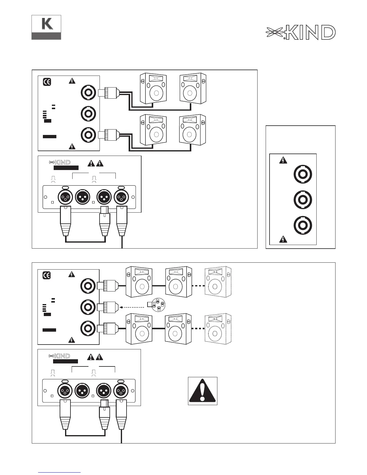
3. Parallel Input
4. Parallel Mono Mode
KQ
Output Mode
Input Wiring / Input - Output Mode Connections
IMPORTANT NOTE: In the parallel
mode both attenuators must be set at
the maximum position (is not possible
adjust the level from the amplifier in
this mode).