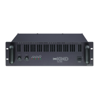
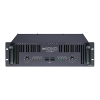
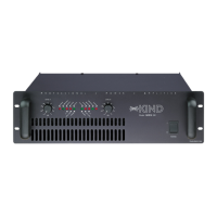
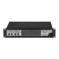
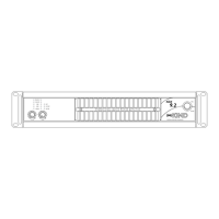
1. Rack mounting ears
Two front panel mounting holes
are provided on each mounting
ear.
2. Standard rack handles
Comfortable handles are provi-
ded for easy transport and
mounting operation.
3. Input attenuators
Two front panel precision 41 pc
input attenuators adjust level for
their respective amplifier chan-
nels. Minimum attenuation (-0dB)
equals maximum output. In the
bridged mode both attenuators
are used to control signal level; in
addition both must be set at the
same setting.
4. Clip/Limiter
Each channel has a LED that
lights at the real clipping points
indipendent from the load or
possible main voltage fluctuation,
and indicates (when switched on)
the limiter engaged.
5. Signal
Each channel has a LED that
lights when the output signal
(before output relay) is greater
than +10dBV.
6. Protect/Temp
Each amplifier has one red pro-
tect LED.When one of the chan-
nels is in protect mode for DC in
the output or high temperature,
LED will light. Internal protection
is fully separated for the chan-
nels, may occur that protect LED
lights up for one channel pro-
blem but the other channel may
work normally.
7.Active
The green active LED illuminates
to indicate that the amplifier is
turned on.
8. Fan exhaust ports
Heated air exits the amplifier
through the exhaust ports, loca-
ted on the front and sides of the
amplifier chassis. Be sure not to
block this ports, especially when
rack-mounting the amplifier.
9.AC power switch
Use this to switch on the ampli-
fier. An advanced soft-start limits
the toroidal transformer surges.
1. Supporti di montaggio
Due fori per il montaggio, ogni
lato, sono previsti sul pannello
frontale.
2. Maniglie standard
Comode maniglie sono fornite
per facilitare operazioni di tra-
sporto e montaggio.
3.Attenuatori di ingresso
Due attenuatori di precisione a
41 pc sono presenti sul pannello
frontale per la taratura rispettiva
di ogni canale dell'amplificatore.
Minima attenuazione (-0dB)
uguale a massima uscita. Nell'uso
a ponte ambedue gli attenuatori
sono usati per controllare il livel-
lo di segnale; inoltre ambedue
devono essere posizionati nella
stessa posizione.
4. Clip/Limiter
Ogni canale ha un LED che lam-
peggia al punto di clip reale indi-
pendentemente dal carico o da
una possibile variazione dell'ali-
mentazione, indica anche (quan-
do inserito) l'intervento del limi-
ter.
5. Signal
Ogni canale ha un LED che lam-
peggia quando il segnale d'uscita
(prima del relé) é maggiore di
+10dBV.
6. Protect/Temp
Ogni amplificatore ha un LED
rosso di protezione. Quando uno
dei canali é in protezione per DC
in uscita oppure alta temperatura
il LED si illumina. Le protezioni
interne sono completamente
separate per i canali, potrebbe
succedere che il LED di protezio-
ne sia illuminato per problemi ad
un canale ma che l'altro canale
lavori normalmente.
7.Active
Il LED verde active si illumina per
indicare che l'amplificatore é
acceso.
8.Aperture di scarico
L'aria per il raffreddamento del-
l'amplificatore viene scaricata sul
fronte e sui fianchi dell'amplifica-
tore attraverso le aperture di
scarico, accertatevi di non ostrui-
re queste aperture specialmente
quando montate a rack l'amplifi-
catore.
9. Pulsante di accensione
Usatelo per accendere l'amplifi-
catore. Un sistema di soft-start
limita l'assorbimento del trasfor-
matore toroidale.