OPERATION CONTROLS
AIR COMPRESSOR PUMP
T
o compress air, the piston moves up and down in the cylinder. On the downstroke,
air is drawn in through the intake valves. The exhaust valves remain closed. On the
upstroke of the piston, air is compressed. The intake valves close and compressed
air is forced out through the exhaust valves.
CHECK VALVE
When the air compressor is operating, the check valve is “open”, allowing
compressed air to enter the air tank. When the air compressor reaches “Cut-Out”
pressure, the check valve “closes”, allowing air pressure to remain inside the air tank.
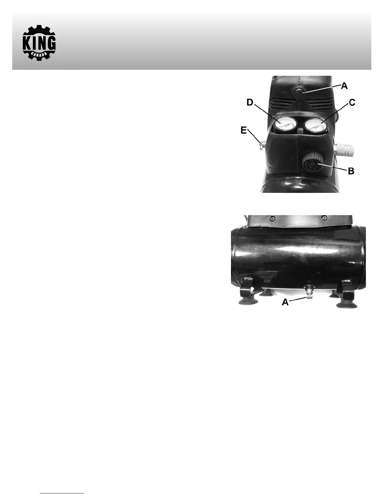
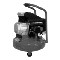
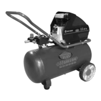
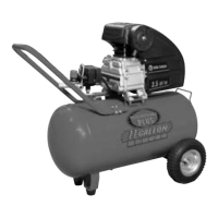
ON/OFF SWITCH (A) FIG.3
Turn this switch ON (press downwards) to provide power to the automatic pressure
switch and OFF to remove power at the end of each use.
PRESSURE SWITCH
The pressure switch automatically starts the motor when the tank pressure drops
below the factory set “Cut-In” pressure. It also stops the motor when the air tank
pressure reaches the factory set “Cut-Out” pressure.
REGULATOR (B) FIG.3
The air pressure coming from the air tank is controlled by the regulator. Turn the
regulator knob clockwise to increase pressure and counterclockwise to decrease
pressure. To avoid minor readjustment after making a change in the pressure setting,
always approach the desired pressure from a lower pressure. When reducing from a
higher to a lower setting, first reduce the pressure less than that desired, then bring it
up to the desired pressure. Depending on the air requirements of each particular
accessory, the outlet regulated air pressure may have to be adjusted while operating
the accessory.
OUTLET PRESSURE GAUGE (C) FIG.3
The outlet pressure gauge indicates the air pressure available at the outlet side of the regulator.
The pressure is controlled by the regulator and
is always less than or equal to the tank pressure.
TANK PRESSURE GAUGE (D) FIG. 3
The tank pressure gauge indicates the reserve air pressure in the tank.
DRAIN VALVE (A) FIG. 4
The drain valve is located at the base of the air tank and is used to drain condensation at the end of each use.
SAFETY
PRESSURE RELEASE V
AL
VE (E) FIG.3
If the pressure switch does not shut off the air compressor at its cutout pressure setting and the air pressure keeps rising, the safety valve will
protect against high pressure by “popping out” above factory set pressure (slightly higher than the pressure switch cut-out setting).
WARNING!: If the safety pressure release valve does not work properly, over pressurization may occur, causing air tank rupture or an explosion.
Daily pull the ring on the safety valve to make sure that the safety valve operates freely
. If the valve is stuck or does not operate smoothly
, it must
be replaced with the same type of valve.
FIGURE 3
FIGURE 4