This document contains manuals for two distinct devices: an Oil-Free Air Compressor Kit (Model: 8440N) and an 18 GA. X 2" Brad Nailer Kit (Model: 8200B), both manufactured by King Canada.
Oil-Free Air Compressor Kit (Model: 8440N)
Function Description:
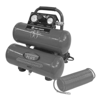
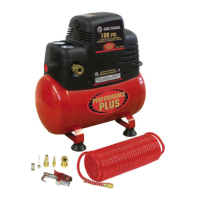
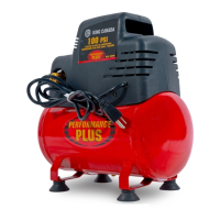
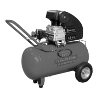
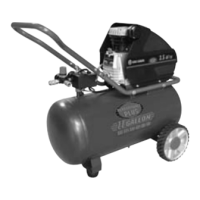
The King Canada Model 8440N is an oil-free air compressor designed to provide compressed air for various applications. It features a compact design with two air tanks and a control panel for managing air pressure. The "oil-free" designation means it does not require oil for lubrication, simplifying maintenance and reducing the risk of oil contamination in the air supply. This compressor is intended for non-commercial use and comes with a 2-year limited warranty.
Important Technical Specifications:
- Model: 8440N
- Voltage: 120V
- Amperage: 3.7A
- RPM (no load speed): 2,900
- Phase: 1
- Hertz: 60Hz
- Maximum operating pressure: 100 PSI
- CFM @ 40 PSI: 0.82
- CFM @ 90 PSI: 0.60
- Tank size: 2 x 1.5 US Gallons (total 3 US Gallons)
- Electrical Connection: Requires a 120V outlet, using a 15-amp time delay fuse or circuit breaker.
- Extension Cord Requirements: The manual recommends using a longer air hose instead of an extension cord to minimize power loss. If an extension cord is necessary, it must be a 3-wire grounding type with appropriate wire gauge based on length (e.g., 0-25 feet: No. 16, 26-50 feet: No. 16, 51-100 feet: No. 14).
Usage Features:
- On/Off Switch (A): Provides power to the automatic pressure switch. Press upwards to turn ON, downwards to turn OFF.
- Pressure Switch: Automatically starts the motor when tank pressure drops below the factory-set "Cut-In" pressure and stops it when the "Cut-Out" pressure is reached.
- Regulator (A): Controls the air pressure coming from the air tank to the outlet. Turn clockwise to increase pressure, counterclockwise to decrease. It's recommended to approach desired pressure from a lower setting to avoid minor readjustments.
- Outlet Pressure Gauge (B): Displays the regulated air pressure available at the outlet, which is always less than or equal to the tank pressure.
- Tank Pressure Gauge (C): Shows the reserve air pressure inside the tank.
- "One Touch" 1/4" Quick Release Coupler (D): Used for connecting air hoses and accessories with a 1/4" male fitting.
- Drain Valve (A): Located at the base of the air tank, used to drain condensed water after each use.
- Safety Pressure Release Valve (A): A crucial safety feature that "pops out" if the pressure switch fails and tank pressure exceeds the factory-set cut-out pressure, preventing over-pressurization, rupture, or explosion. Users are instructed to pull the ring daily to ensure it operates freely.
- Setup and Operation:
- Operate in a dry, clean, cool, and well-ventilated area, at least 12 inches away from walls or obstructions.
- Ensure the On/Off switch is OFF and the air regulator is closed before attaching hoses or accessories.
- Attach the coil hose and optional air tools/accessories using 1/4" male fittings and the quick connect coupler. Teflon tape is recommended for threads to prevent leaks.
- Turn the switch ON and allow tank pressure to build until the motor stops.
- Open the regulator by turning it clockwise and adjust to the desired pressure setting, ensuring it does not exceed the maximum pressure rating of the air tool being used.
- Storing: After use, turn the switch OFF, set the regulator to zero, disconnect tools, pull the safety valve ring to bleed tank pressure to approximately 20 psi, then open the drain valve to completely drain water from the tank. Close the drain valve before storing.
Maintenance Features:
- Daily/Before Each Use:
- Drain condensation from the tank.
- Check for unusual noise or vibration.
- Ensure all nuts and bolts are tight.
- Keep Tool Clean: Periodically blow out air passages with dry compressed air. Clean plastic parts with a soft damp cloth. Avoid solvents.
- Grounding: The compressor must be properly grounded to prevent electrical shock. The power cord has an equipment-grounding conductor and a grounding plug. Do not remove or alter the grounding prong.
- Troubleshooting Chart: Provides solutions for common issues like:
- No start condition: Blown fuse/breaker, loose electrical connections, overheated motor.
- Low pressure: Air leak in safety valve, defective check valve.
- Safety valve releasing: Defective pressure switch or improper adjustment.
- Tank pressure drops when compressor shuts off: Loose drain valve, loose connections at regulator or pressure switch.
- Excessive moisture coming out of air hose: Excessive water in the tank, high humidity.
Safety Instructions:
- Risk of Explosion or Fire: Operate in a well-ventilated area, away from flammable materials (at least 20 feet if spraying flammable materials). Do not restrict ventilation openings. Always remain in attendance when operating.
- Risk of Bursting: Drain tank daily. Never drill into, weld, or modify the tank or its attachments. Do not alter factory-set operating pressures. Ensure attachments and accessories do not exceed their operating pressure.
- Risk of Burns: Avoid touching exposed metal parts during or immediately after operation, as they remain hot for several minutes. Allow the compressor to cool before maintenance.
- Risk of Property Damage When Transporting: Place the compressor on a protective mat during transport to prevent oil leaks and remove it immediately upon arrival.
- Electrical Safety: All electrical connections must be done by a qualified electrician. Disconnect the compressor from the power source before any adjustments or repairs.
GA. X 2" Brad Nailer Kit (Model: 8200B)
Function Description:
The King Canada Model 8200B is an 18 gauge brad nailer designed for driving finish nails ranging from 5/8" to 2" in length. It operates on compressed air and is suitable for various woodworking and finishing tasks. This tool is intended for non-commercial use and comes with a 2-year limited warranty.
Important Technical Specifications:
- Model: 8200B
- Air inlet: 1/4" NPT
- Maximum permissible operating pressure: 120 PSIG (8.3 bar)
- Recommended operating pressure range: 70-100 PSI
- Nail range: 5/8" to 2" 18ga. brad head finish nails
- Nail width: 1.25mm
- Nail thickness: 2mm
- Nail capacity: 100 brad nails
- Compatible Brad Nails (King Industrial):
- BN-1816: 5/8" (16mm approx.)
- BN-1820: 3/4" (18mm approx.)
- BN-1825: 1" (25mm approx.)
- BN-1830: 1 3/16" (29mm approx.)
- BN-1832: 1-1/4" (30mm approx.)
- BN-1838: 1-1/2" (36mm approx.)
- BN-1840: 1-9/16" (38mm approx.)
- BN-1845: 1-3/4" (42mm approx.)
- BN-1850: 2" (50mm approx.)
Usage Features:
- Air Deflector: Directs exhaust air away from the user.
- Trigger: Activates the nailer.
- Magazine Latch: Releases the magazine cover for loading nails.
- Magazine: Holds up to 100 brad nails.
- Safety Release: A mechanism that prevents accidental firing.
- Nail Loading Area: Where nails are inserted into the magazine.
- Nail Discharge Area: Where nails exit the tool.
- Operational Modes:
- Sequential Mode: Recommended for precise nail placement. Requires depressing the nailer nose against the workpiece, then pulling and releasing the trigger for each nail.
- Bump Fire Mode: Recommended for less precise nail placement. Requires depressing the trigger, then tapping the nailer nose against the workpiece for each nail.
- Verification of Safety Trip Mechanism: Before use, disconnect air, empty nails, ensure trigger and safety trip move freely. Connect air, depress safety trip without pulling trigger (tool must not cycle). Hold clear of workpiece, pull trigger (tool must not cycle). Depress safety trip and pull trigger (tool must cycle).
- Loading Nailer Magazine:
- Disconnect air hose.
- Depress magazine latch and pull back the cover.
- Insert a stick of nails, ensuring pointed ends are close to the bottom edge and nail heads align with the machined groove.
- Push magazine cover forward until the latch catches.
- Operating Your Nailer:
- Add 1-2 drops of 30W oil for air tools into the air inlet.
- Install a quick connect fitting to the nailer.
- Connect to an air compressor using a 3/8" I.D. hose with a rated working pressure exceeding 200 psi and a female quick coupler.
- Regulate air pressure to 85 psi.
- Load nails into the magazine.
- Reconnect the air hose.
- Test nail penetration on scrap wood, adjusting air pressure (up to 100 psi) until desired penetration is achieved.
Maintenance Features:
- Lubrication:
- Lubricate before and after the first use, and periodically thereafter.
- Disconnect air supply.
- Turn nailer inlet up, add ONE DROP of high-speed spindle oil (or oil without detergent) into the air inlet. Operate briefly after oiling.
- Wipe off excessive oil from the exhaust.
- If an in-line oiler is used, daily manual lubrication is not required.
- Air Supply and Connections:
- The manual illustrates the correct connection mode: Compressor -> Filter -> Oiler -> Regulator -> Quick Couplers -> Air Hose -> Quick Connector -> Nailer.
- Oiler: Recommended for continuous lubrication and increased tool life. Check oil level daily.
- Filter: Recommended to remove moisture and impurities, increasing tool efficiency and life. Check and drain daily.
- Quick Connector/Coupler: For better performance, install a 3/8" quick connector (1/4" NPT threads) with a 0.315" inside diameter on the tool and a 3/8" quick coupler on the air hose.
- Cleaning Your Nailer:
- Never use gasoline or other flammable liquids.
- Disconnect air supply.
- Remove tar buildup with #2 kerosene fuel oil or diesel fuel. Avoid getting solvent into the cylinder. Dry the tool completely before use.
- Clearing Jams:
- Disconnect from air compressor.
- Disconnect air hose.
- Depress magazine latch, pull back cover, and remove all nails.
- Undo the three cap screws (A), remove front plate (B) and intermediary plate (C).
- Use pliers to remove the jammed nail from the nail discharge area (D).
- Reinstall all parts in reverse order and secure with the cap screws.
- Troubleshooting Chart: Provides solutions for common issues like:
- Air leaking at trigger valve area: Damaged O-rings.
- Air leaking between housing and nose: Loose screws, damaged O-rings, bumper damage.
- Air leaking between housing and cap assembly: Loose screws, damaged seal.
- Nailer skips a nail: Worn bumper, dirt in nailer nose, nails not moving freely, inadequate air flow.
- Nailer runs too slowly or has loss of power: Worn O-ring on piston, lack of lubrication, damaged O-rings on trigger valve, air leaks, cap seal leaking, insufficient lubrication, broken spring in cap assembly, blocked exhaust port.
- Jammed nails: Worn/damaged driver guide, bent nails, loose magazine/nose screws, damaged driver.
- Replacement Driver, Bumper & O-Ring Repair Kits: A complete kit (Model: KW-117) is available for replacing internal O-rings, bumper, and driver due to wear and tear.
Safety Instructions:
- Read and understand the manual and all safety instructions.
- Never use flammable gases as a power source; use filtered, lubricated, and regulated compressed air only.
- Never use gasoline or other flammable liquids to clean the nailer, as vapors can ignite and cause explosion.
- Do not exceed 120 PSIG operating pressure.
- Disconnect from air supply before clearing jams, servicing, adjusting, or when not in use.
- Do not keep the trigger pulled on the contact safety trip mechanism when carrying or holding the nailer. Never carry by the air hose or pull on the air hose to move the nailer.
- Always wear Z87 safety glasses with side shields, hearing, and head protection at the workplace.
- Do not use a check valve or any fitting that allows air to remain in the nailer.
- Do not place hands or any body part in the nail discharge area when connecting or disconnecting from the air supply.
- Never point any operational nail driving tool at yourself or others.