!
The control unit has been designed to manage one 24Vdc motors gate automations.
To start the system it is necessary to:
1- Connect the power supply and the accessories as indicated in the 2nd paragraph
2- Set the dip-switches (paragraph 4A) and the trimmers (paragraph 4B) depending on the wanted functioning and on the
conditions of the system.
3- Perform the standard programming procedure (paragraph 6B) or the professional programming procedure (paragraph 6D), to
recognize the starting point and the end point of the travel.
4- Perform the checks reported on paragraph 6C (warning before starting).
If the control unit keeps on having problems after these steps, see paragraph 9 “Signaling led”, to identify possible
anomalies, and paragraph 14 “inconvenient and remedy” to try to eliminate them.
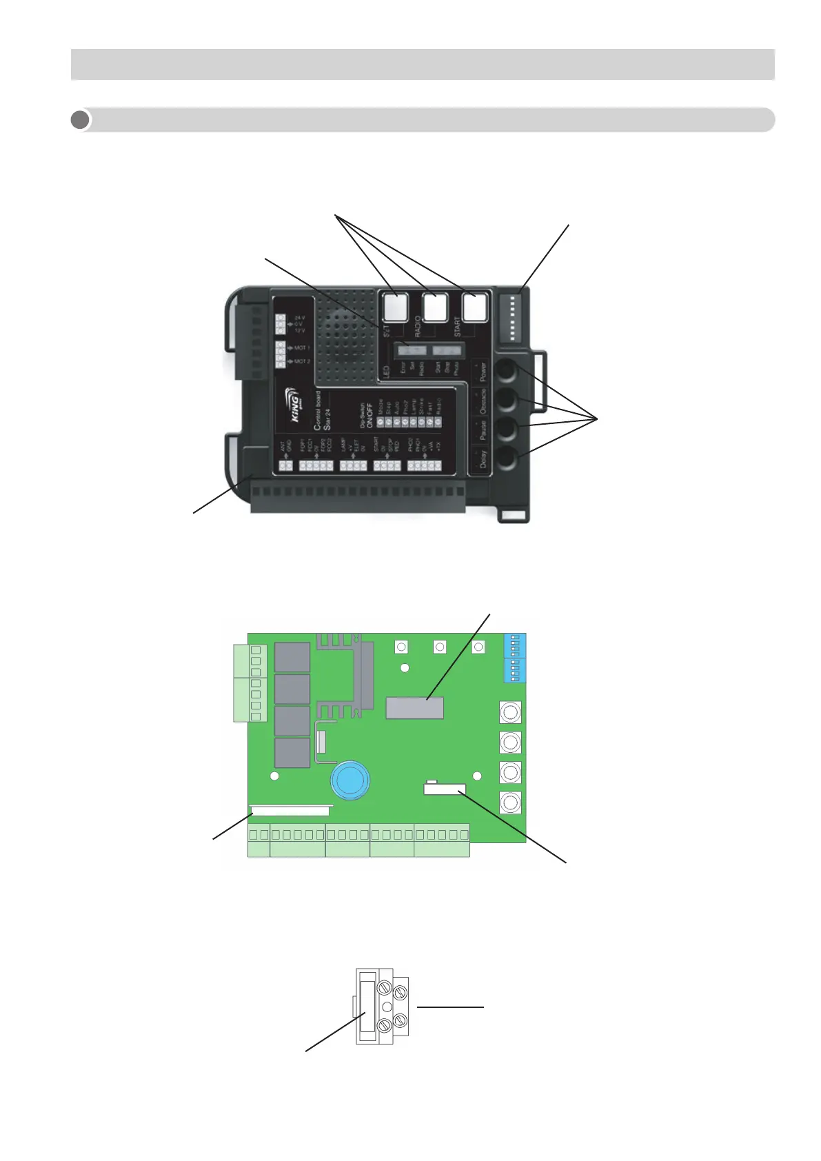
1B - STARTING MODALITY
- Management and control for one 24Vdc motors (terminals 24,25).
- Opening-closing limit switch inputs (terminals 3,4,5).
- 433.920Mhz rolling code built-in receiver (code: “RX STAR”, see paragraph 1A – 13B).
- Removable memory (code: “MEMO”) containing up to 180 memorized radio codes (paragraph 1A - 13A).
- 6 signaling led (paragraph 1A – 9).
- Predisposition for the battery charge card and the 24Vdc batteries up to 7Ah (optional) (see paragraph 12D).
- Predisposition for the 230 Vac card for courtesy light control connection (max 500W, optional) (see paragraph 12E).
- Customizable and differentiable slow down in opening and closing thanks to the professional learning procedure (see
paragraph 6D).
- Built-in lamp intermittent manager (see paragraph 12A).
- Customizable pedestrian opening by pedestrian programming procedure (see paragraph 7).
- Customizable prelamp from 0 to 5 sec. by trimmer (see paragraph 4B)
- Pause time before automatic reclosing customizable from 0 to 90 sec. by trimmer (see paragraph 4B).
- Sensibility of the intervention adjustable from 0.1 to 3 sec. by trimmer (see paragraph 4B).
- Power/speed adjustable from 50% to 100% by trimmer (see paragraph 4B).
- Input for control-by-wire to manage start, stop and pedestrian opening.
- Double safety inputs: closing (terminal 16) and opening and closing (terminal 17).
- Input for warning light to signal the wing position (see paragraph 12C).
1C - MAIN FEATURES
If you perform the standard programming procedure (see paragraph 6B), and there are no modifications on the trimmer regula-
tion (see paragraph 4B) and on dip switches (see paragraph 4A), the control unit will act as follows:
- The safety devices in closing, connected to “PHO1” contact (terminal 16), will intervene only in closing, inverting the motion.
- The safety devices in opening, connected to “PHO2” contact (terminal 17), will intervene both in closing and in opening,
keeping on the motion when the device has been cleared (setting by the dip 4 “PHO2”).
- Pause time before automatic reclosing equal to 45 seconds.
- Pedestrian opening procedure controlled by cable and by transmittter (if the transmitter has been programmed by the
procedure as per paragraph 3b) and with an half of the total opening.
- The slowdowns are set to the final 15% of the travel.
1E - PRESETS
Control unit supply 230 Vac
Secondary 1 transformer 12 Vdc
Primary transformer 230 Vac
Secondary 2 transformer 24 Vdc
12 Vdc, max 250mA, protected by fuse Photocells output
24 Vdc, max 15W, protected by fuse Flashing lamp output (Terminals 8,9)
12 Vdc, max 3W, protected by fuse Open gate warning light output (Terminals 18,20)
-20 ÷ +55 Working temperature
150Va Transformer power
Motor output 24 Vdc (Maximum 120Watt)
1D - TECHNICAL DATA
 Loading...